So I am trying to model a disk with the surface being a series of rings made by alternating inclined planes. This may be a simple thing but this is my first attempt at 3D modeling. I originally made the design with the intention of using a CNC router to create the piece using a depth map but the CNC could not get the fine details at the scale I wanted so now I am using a binder jet 3D printer to create it and I am having great results using the depth map and Photoshop’s extrude from depth map feature. The problem is that the end product is more than just the disk so when I bring the model (as a .stl) into Blender its far too complicated to edit further with any accuracy. I should most likely be using some sort of 3D CAD software but this isnt something I do often. I am wondering if there is a similar feature in blender, or if I could potentially model the rest of the piece and then texture the face with the depth map and extrude the planes from that base shape. I am attaching a photo of the 3D printed prototype of just the disks face as well as a line drawing and the depth map to get a better feel for what I am talking about. The end product should have a border protruding out of the back about 1" with a 1/4" wall thickness. There will also be cavities on the back side of the face inside of the cylinder shaped border.
It would be a lot of work in a cad application, might be easier in Blender with a base shape and a radial deformer, but I’m new to Blender. In another 3d poly modeling app sometimes the deformers don’t give very precise control, which appears to be crucial for this form. The only app I know of that does give fairly precise control over radial deform with meshes is FormZ.
I think you will need to build this from scratch in order to do additional work to it. I’ve made some models from heightmaps in ZBrush and other apps. If Photoshop works in a similar way, all edges that are not perfectly horizontal or vertical with respect to the grid suffer from a rasterized (stairstep) effect.
Your last image certainly looks like the inside surface of one ring falls on the same diameter as the outside surface of the adjacent ring.
I don’t see how you generated the different diameters and keep them precisely the right size to fit inside each other. Could you indicate how you did that?
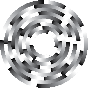
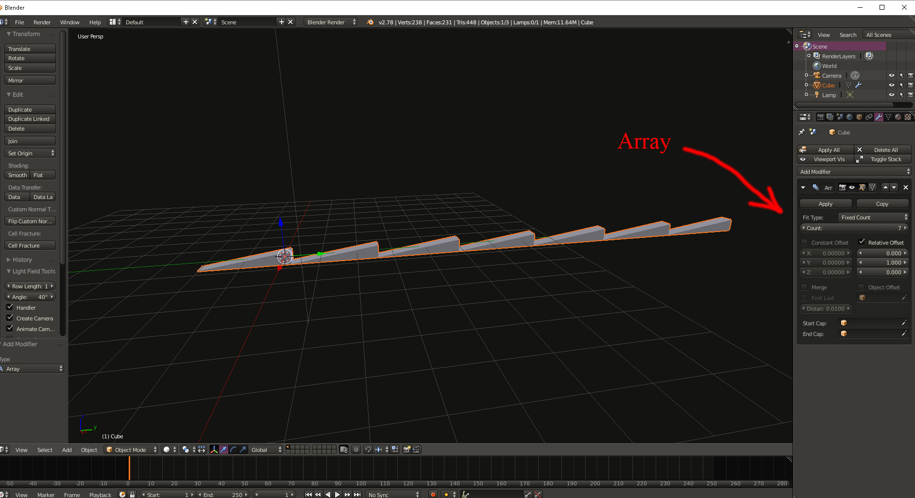
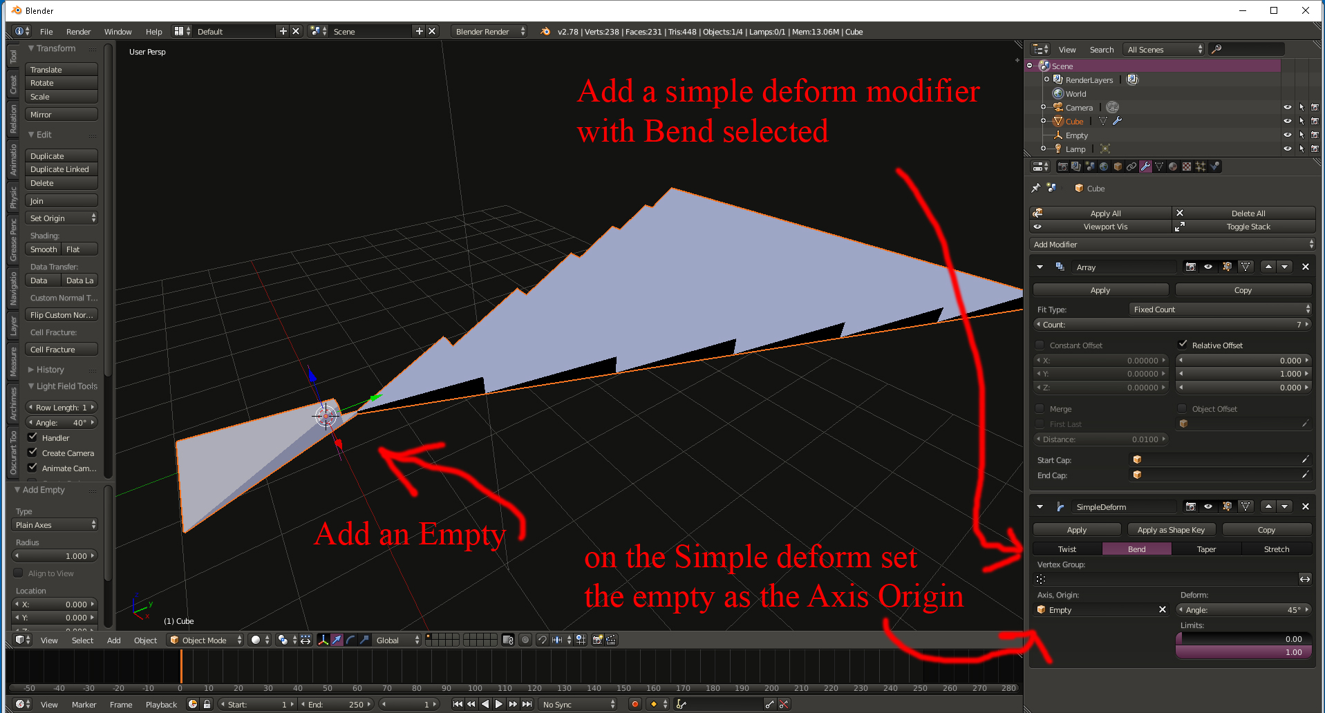
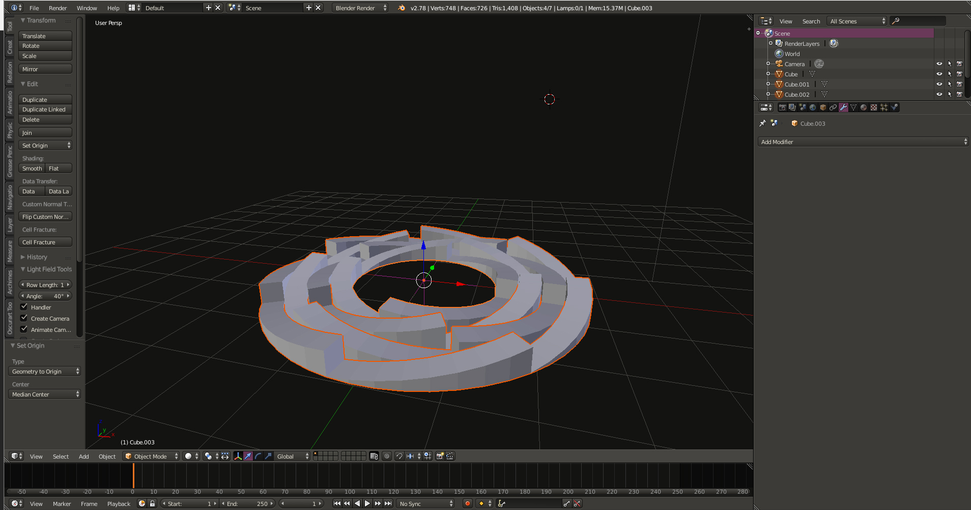
Make the 1st ring -->Leave the array and simple deform on --> Duplicate the ring -->.on the duplicate change the deform angle to minus 360 (-360) --> this will flip the rings direction --> Alternate between 360 and -360 as you create each successive ring --> on the duplicate reduce the count by 1 -->This will shrink each successive ring --> after creating all the rings apply the modifiers --> They wont be lined up because their origin is centered on the 1st wedge in the array --> After applying the modifier you will be dealing with real geometry --> Select them all --> space bar --> Snap Cursor menu --> Snap menu --> Geometry to origin --> This will center them all -->there will probably be a little gap -->you can adjust this by (scaling) S then shift+z will scale in the X and Y direction but not Z (up). I hope this helps you.
Thanks, I missed that … was looking for some kind of offset value instead of count. I guess it divides out the offset by the number of copies so they fit exactly inside each other.