Commit done,
Should be the last one (hope so)
Stephen,
The addon now loads.
There is a separate Archipack tab, left panel.
Unlike the video, there is no Archipack 2d menu under Tools tab. I found it elsewhere.
Interesting! Testing… ty
I’ll get back tomorrow
That is becasue the software has been updated but the video that are supposed to show how to use it have not been updated in a long long time. You just have to search back through that thread and in that feature list that they call the documentation and hope to find the answer that you are looking for.
Dear Stephen,
I have now tested your Archipack. I’m a picky, demanding user, an architect using CAD since 1985 (AutoCAD and now Draftsight) and 3D and rendering software since 1990 (Blender for last 3 years) - I will start with Wow!
This Archipack v-1.3.4 works and is elegant. I’ll start with the specific tests using dxf import from my 2D plans, which creates curve 2D objects. The addon makes windows and doors with ease, correctly and efficiently.
Next step (as your video shows) is the actual walls and the boolean operation. I was not able to actually automatically have the room outlines, as the video shows. I was able to convert a mesh I “raised” from the bezier plan and identify that as “kinda” wall, so that boolean worked (To do so, open a python console and with your wall mesh selected and active type “C.object.data.archipack_wall.add()”)
But those were work-arounds: Your wall interface works so well ! It was very easy to redo the walls quickly and correctly, snapping to the existing plan in the background. These walls, have all the advantages of being fully manipulated later on (not so with the “converted” wall mesh).
Very-very important : the interface is so elegant, with the overlay of information and the side-menus.
Still more: beautiful how the objects can be handled with the addon yet the basic transformations also work with Blender. A very nice related detail, I can substitute the mesh of all identical windows with one - the same - mesh and editing one will edit all, yet the manipulation tools work and the objects remain parametrical
I would write more, but no time right now.
Thank you! very nice
PS: obviously you work too fast to keep your documentation and tutorials to date. It’s a shame, because with good documentation and with workflow examples, this addon would get more attention that it deserves and will help many.
Hi csimeon,
I’m aware of the lack of documentation for 2d to 3d tools and good tutorials, but the shapely dep was a major drawnback and while searching for a strong alternative i wanted to avoid making too much documentation for it as the old doc will remain forever online and may be confusing and time consuming.
I now see users making walls without the “draw a wall” tool wich is one of the most powerfull way of creating them, simply because they saw the first demo ever released.
With the “pygeos” alternative done, i’m able to expose a more powerfull 2d toolset - including boolean, buffers, outlines, simplify …
As this feature set is now available everywhere and is more likely to freeze, video tutorial for this part will follow in next days or weeks, as i also have to do some “commercial” work.
The tools of the “detect” (polygonize) panel still require some love, as they are not all consistent in the way they work.
The 2d to 3d tool does provide her own kind of wall dumb -mesh based-, wich is not the same as “regular” wall entity.
A workaround may be extracting polygons and lines and then use the “wall from curve” to get regular editable walls.
Good morning Stephen,
Can individual wall segments have different thickness?
Is a “T” intersection 2 walls? Is there a snap (other than blender snaps, during creation) wall feature to keep them related?
And I guess an “X” intersection is 3 walls minimum? (One wall going through and two walls on either side of it)
Walls are ment to support (planed) energy simulations, and so they won’t support different thickness per segment as this also means different physical parameter on segment basis.
Yes a T part is an intersection where a X is 2 T parts.
Not only the tool does snap the child but when you “manipulate” the parent, the child will follow according, including every doors and windows on it.
The trick here is to keep your mouse over the parent wall when creating the child using “draw a wall” tool, so the tool know you want to link the child.
See T child wall on the wiki for other options to create and manage such linked childs.
Thank you that is clear and it works fine.
I have a couple of remarks:
1- I would like to be able to tag a mesh as a wall, without the use of a python command. (To have the advantages of Autoboolean, even if I don’t get the full wall functionality)
2- I would like to be able to remove the archipack properties at some point late un my workflow. That way Archipack will not automatically regenerate my topology. This will come in handy for many reasons late in the progress : For example walls have a solidify modifier and are really one surface. This is good for quick and efficient modelling but not so good when you want to assign materials to render. Or one may simply want to customise windows doors or other objects.
And a couple more questions:
Is there a window type with shutters?
Would you be interested in scaled materials, where you don’t have to UV unwrapping? instead you set the scale of a pattern by defining its size in model units.
Hi csimeon,
The 2d to 3d tool provide a “wall” button in polygons section, intended to allow selection of the polygons you want and building a tagged wall for you.
Next release will include “Kill parameters” and “Apply holes” in tools.
Shutters are not yet done, but the panel code is able to handle them, so near ready to start implementation.
I’m still not expert in material setup under blender, so a contribution in a “ready to render” material library is welcome.
As a side note, most archipack objects are uv-mapped out of the box, so there is no need to unwrap (think about unwrapping a stair …).
There is an exception: the way walls are done yet dosent allow it.
Hi Stephen,
Wonderful news! “Kill parameters” was one of my requests and “apply holes” similar and also useful, I think.
Nice! are you thinking they will be part of the same window, an additional parent linked to the one window parent, or a different item?
Not exactly what I was considering and I’ll tell you why why my request would be useful. Forget 2D stuff and consider I have made a wall that has protrusions or varying thickness or whatever existing wall design, not done in Archipack from start. In this case the 2D-3D tools are useless since I don’t start with 2D, the polygon option is under that menu (which is unavailable when a mesh is selected). You had given me the option to type in python “C.object.data.archipack_wall.add()” , I think a button for that would be very useful.
Let me know where I can send you a blend file with custom node group.
Let me start by saying I was pleasantly surprised that the faces generated by solidify modifier, such as Archipack walls, can have separate materials asigned! with slots (without a need to apply and destroy, surfaces exist as entities in edit mode and can be “slotted”).
About not being able to UV unwrap, I think you will find a material with “model scale factor”, as I offered you, very-very appropriate and useful.
Good evening,
Christos
Dear Stephen,
I went ahead and used your addon in a work in progress (architectural design of a house). You can find the report on the progress in the forums, this thread.
The process of using Archipack has been fruitful and we (me and one more architect on the project) are establishing a workflow that is productive! already from the first attempts. This is due in large, to the way you have structured your program, the components and the hierarchy they are made, allow us to use it to complement Blender smoothly.
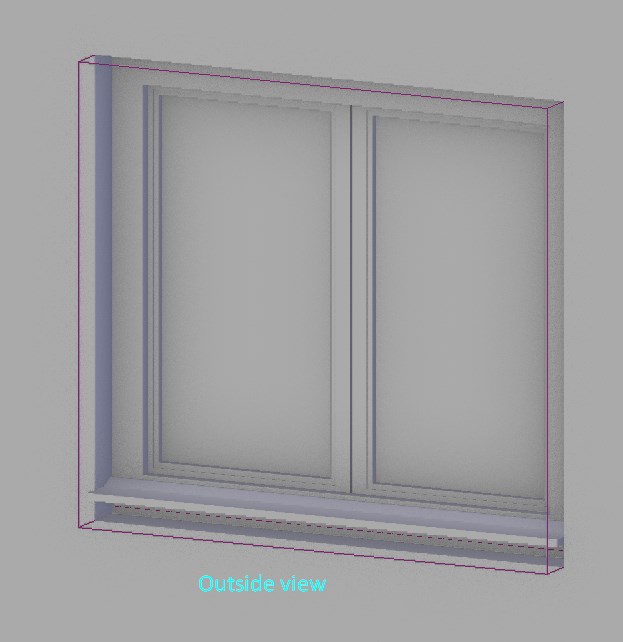
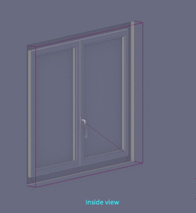
We have set the windows in walls, and the generation of the basic window types “hole” boxing saved us time, effort during creation and we still benefit during editing. A major advantage is the ability to link “window” and “door” objects of the same type to a common mesh, while the program retains the parametric capabilities: the benefit is amazing! we can adjust one window and have automatic updating of all windows, doors of the same type! (of course if I decide to customize the window in any way other than the parameters, I would have to “kill” the parameters, because each parameter manipulation would destroy customization).
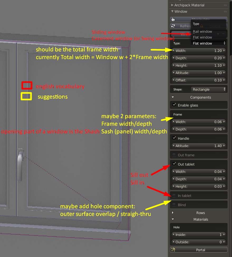
The point I want to make today regards the way the program constructs windows. Archimesh has two types of windows, at the moment, these are the flat window (meaning all window opening panels are level with each other, when closed) and the railing windows (where the panels are offset, so they can slide on rails over each other when they open).
The industry terminology for these window types are:
- Swing windows, that turn usually on vertical hinges, usually inward and sometimes also tilt — this is Archipack flat window.
- The Archipack flat window type also generates what industry calls a Fixed window, which has no opening part, but only frame and glazing. In the industry also, fixed windows are made of the same frame components as swing windows but without the openings.
- Sliding windows, that slide on horizontal rails to open, either in a wall pocket or in parts over each other — this is Archipack railing window
Other common window types (not currently supported by Archipack… I think, forgive me if wrong Sthephen) include the following - Sash (or hung) windows, a very common type in the Anglo-saxon traditional architecture, are windows that slide on vertical rails over each other. Sash windows were so common in USA and England, that the inner frame or the opening part of a window, , is commonly called the sash.
- Awning windows, that tilt open on an horizontal axis, usually outward hinged at the top
The above 5 types, I guess cover about 90% of the window installments. Others that come to mind are pivot (horizontal or vertical axis) windows and multi panel folding windows.
In my professional opinion as an architect, I believe there is a misconception, as to how an Archipack window “fits” a wall. Archipack creates a staggered hole in the wall. In almost all cases cutouts in walls for windows are not staggered that way, but cut straight through instead, this is true both for masonry (brick, stone or concrete) and frame walls (timber or metal).
What makes most windows frames seem wider on the inside than the outside, is that commonly there is a trim around the frame to cover the wall-to-window joint. This trim is an additional piece in most carpentry work, nailed to the frame, or clip fit.
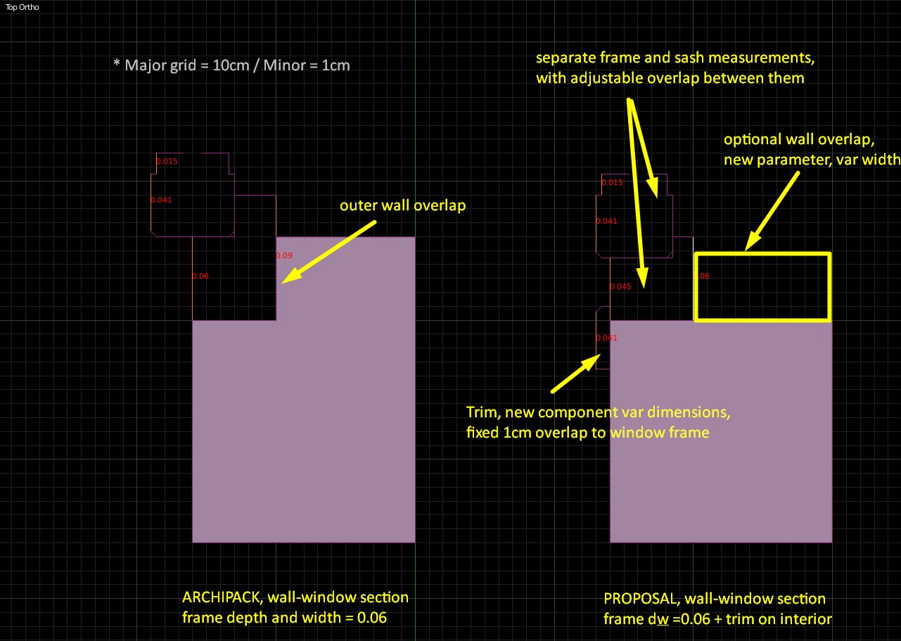
Archipack on the other hand has the wall overlap the frame. The few cases I can think of this happening is facades sometimes with facade cladding or with external insulation finish (EIFS) and then only with some details. An Archipack example of a window 1.00m wide with a .06m frame, measures 1.12 from the inside and 1.00 meter on the outside. From the outside you only see the sash (glazing frame) 0.06 on all sides, while on the inside you see .06+.06 frame and sash on each side. This is not what happens in a typical window situation. The window frame measurement is the wall opening measurement minus tolerances only (no staggering in cutout) and you see frame and sash (.06+.06) inside and out, inside you often have an additional trim. Please see sketches below
Below are two diagramatic sketches of a swing window to wall detail, in plan, flush inside at top and intermediate at bottom:
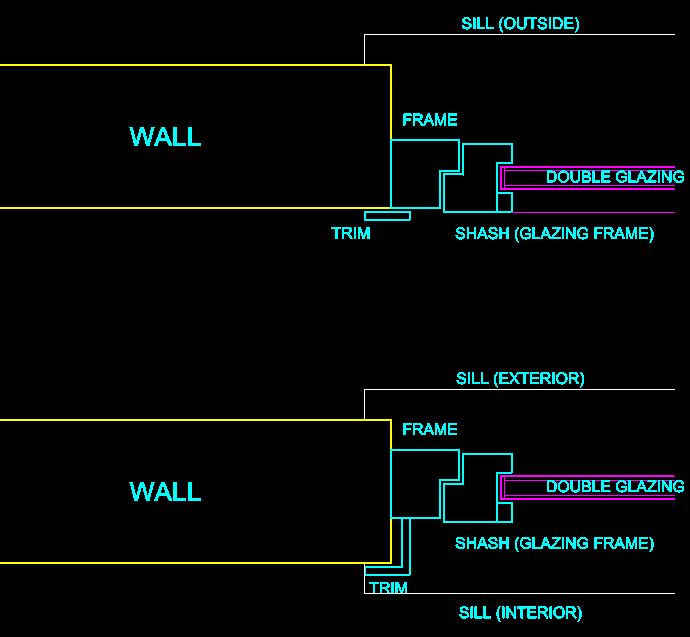
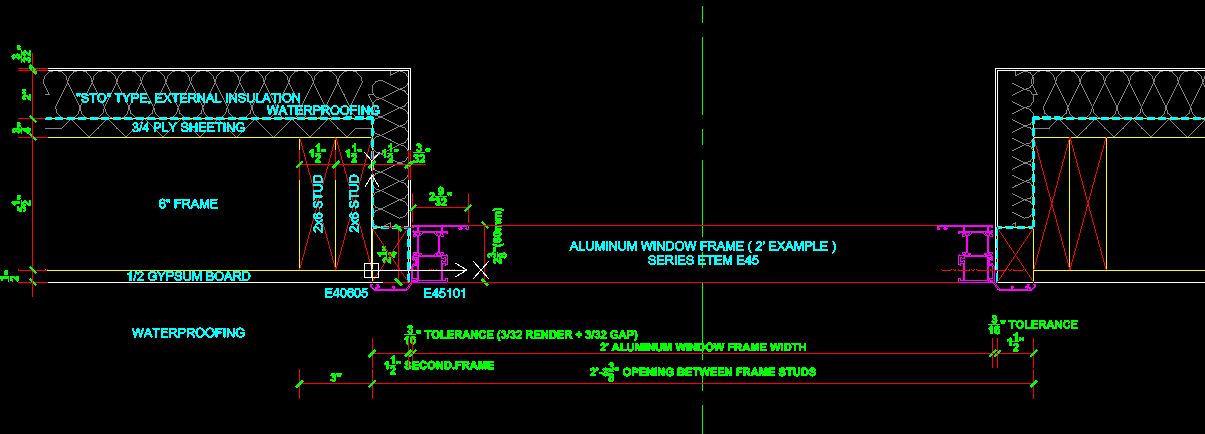
And below is an example from a real project of mine, in the USA, with a timber frame wall and an aluminum window. The window is flush inside, I have only drawn the frame profile (not the sash) and this particular frame profile has an integrated trim that overlaps the wall (to be installed flush inside and mounted from the inside, pushed out into place)
Hi Christos,
You’re right, archipack’s windows are still not US like design friendly, and many english architectural words are lacking.
At least there are some shared properties, the width and height are the size of opening done in the wall, so we probably are able to handle both using the same data model.
Staggered holes are in fact two straight holes done in multi-layer walls where the windows lie against exterior layer
eg:
- Outside layer, wood/concrete
- Thermal insulation
- Inside layer (wood/concrete/plaster…)
Sample of typical european design for windows Norba (move down a bit to see details)
Attachments
Actually I live and practice in Greece, work in the USA was a recent assignment overseas.
In my 35 years of practice, I can think of only a couple projects with staggered wall cutout. I guess France is different.
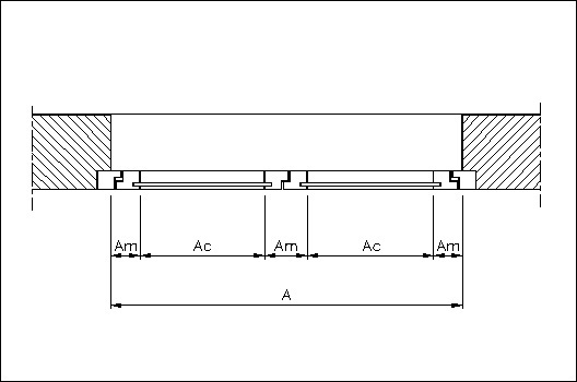
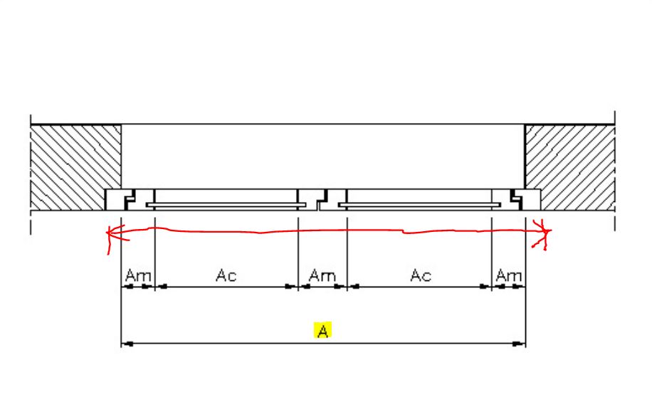
Most importantly however, even for detailing like that of the image you posted (outside wall partially covering window frame), the width (and height) of the window, as given in window schedules by architects and as understood by manufacturers is the total width of frame and not the outer wall opening that may or may not overlap the frame. In the image below, the red dimension is the window width, not the one labeled “A”, which is the window opening.
Can you think of a solution? to serve both cases, maybe one more parameter to specify the outer wall overlap (hole set back dimension)?
My first 3D CG programming was in the early eighties… at Cornell University computer labs. Our monitors there were bw vector driven (they did not scan all pixels left right, top bottom) and input was punch cards… the computer filled a room. My latest was customizing Autocad with LISP, about 20 years ago.
You think it’s time I give Python a try? May I help? Haha
Hi Christos,
Width and height refer to the hole done in the outside part of the wall, so this is the same in both staggered and straight model.
I should add a “frame overflow” parameter, when set to 0, the frame fit with size as you suggested, and when > 0 the frame overflow as in many north european country.
Sill in and out also will require an altitude parameter.
Hole probably also may require an “overflow” parameter to handle inside overflow not exactly fitting frame.
Note: hole allready is able to overflow on outside, to allow negative joints.
I had my first attempts at editing Python… I managed to make both hole cutouts the same as I want.
Your thoughts on allowing flow overflow as a parameter, choice for user input, are certainly better!
For the moment I changed line #775 or archipack_window.py from x0 = 0 :
if self.out_frame is False:
            <i><b>x0 = -self.frame_x</b></i>
        else:
            x0 = -min(self.frame_x - 0.001, self.out_frame_y + self.out_frame_offset)
That works fine for removing overlap of outer wall surface. As you already said the sill (tablet) needs to be lowered and the frame on the outside is too wide (9cm)
Heads up : hole profile is done in 3 parts, outside, overflow and inside.
If you need a 0 overflow, then you must remove one part of the profile to prevent boolean errors with degenerate faces.
Find hole profile in code and setup like this:
    # Hole without overflow
    return WindowPanel(
        False,     # closed
        [0, 0, 0],     # x index
        [x0],
        [y_outside, y0, y_inside],
        [outside_mat, inside_mat],     # material index
        side_cap_front=2,     # cap index
        side_cap_back=0
)If i can add my own experience from Belgrade / Serbia / western Balkans region. In about 99% cases in residential architecture of all types, window sits as shown in Norba link stephen_leger gave, the first and third case. The wall is usually consisted of a thicker structural layer 20 - 25 cm in width and a thermal layer 10 - 15 cm thick. There is an optional third layer of cladding in luxurious projects but it is rare. The window always sits at the end of the structural layer and touches the thermal layer (exactly as shown in the Norba link). So the opening hole has visible side surfaces in exterior as well as in interior and has exterior sill made of tin metal and interior sill usually made of wood or PVC. In most cases it is a swing window with a tilt option (opening to inside). Sometimes, there is a thermal layer overlap and the dimension of the window in technical docs and drawings is the dimension of the structural layer opening.
Sorry if I did not read every single Thread.
But if you need help to create a library for Windowstypes all over the world then let me know - I have some knowledge in typical swiss windows constructions.
But this also could be obsolete because Stephen Ledger is implementing the possibility to create your own Windows-Construction-Details (not only the given Parameters like in the current state of the Addon).