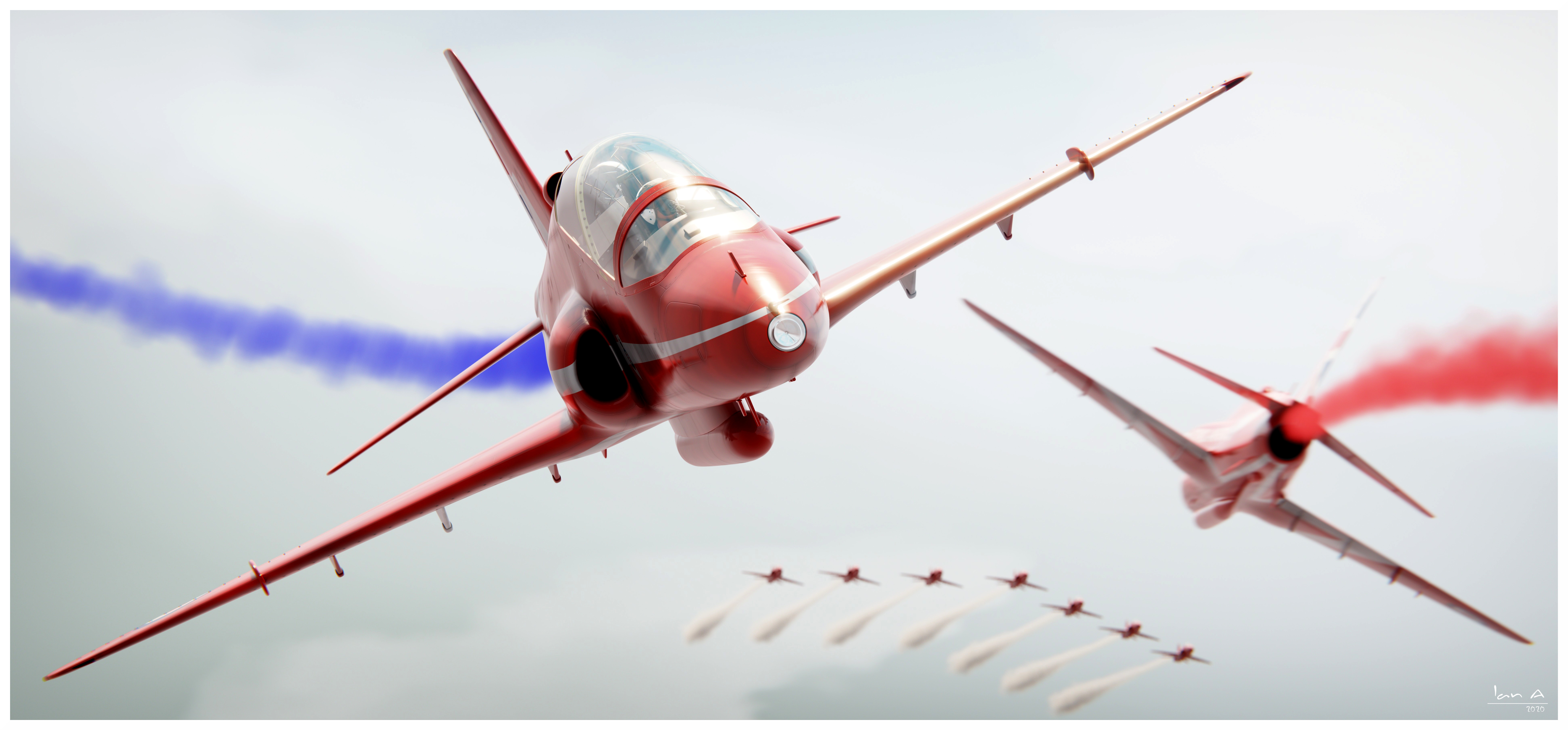
It’s been a while since I’ve posted anything so thought I’d try and get back into the swing of it. Here’s a Hawk model I that originally did a couple of years ago but have revisited over the last few days.
Fairly pleased with how it came out, though I definitely need some more practice with the smoke simulation…
Outstanding!
Critiques? I’ve stood next to these aircraft and chatted with the pilots. The leading edges of the wings have blackened deposits from smoke but the rest of the aircraft are very polished.
Only other thing is the cockpit canopy which is clear and not yellow in real life.
Other than that though, these look bloom’in near photorealistic!!!
Jolly good show old chap :o)
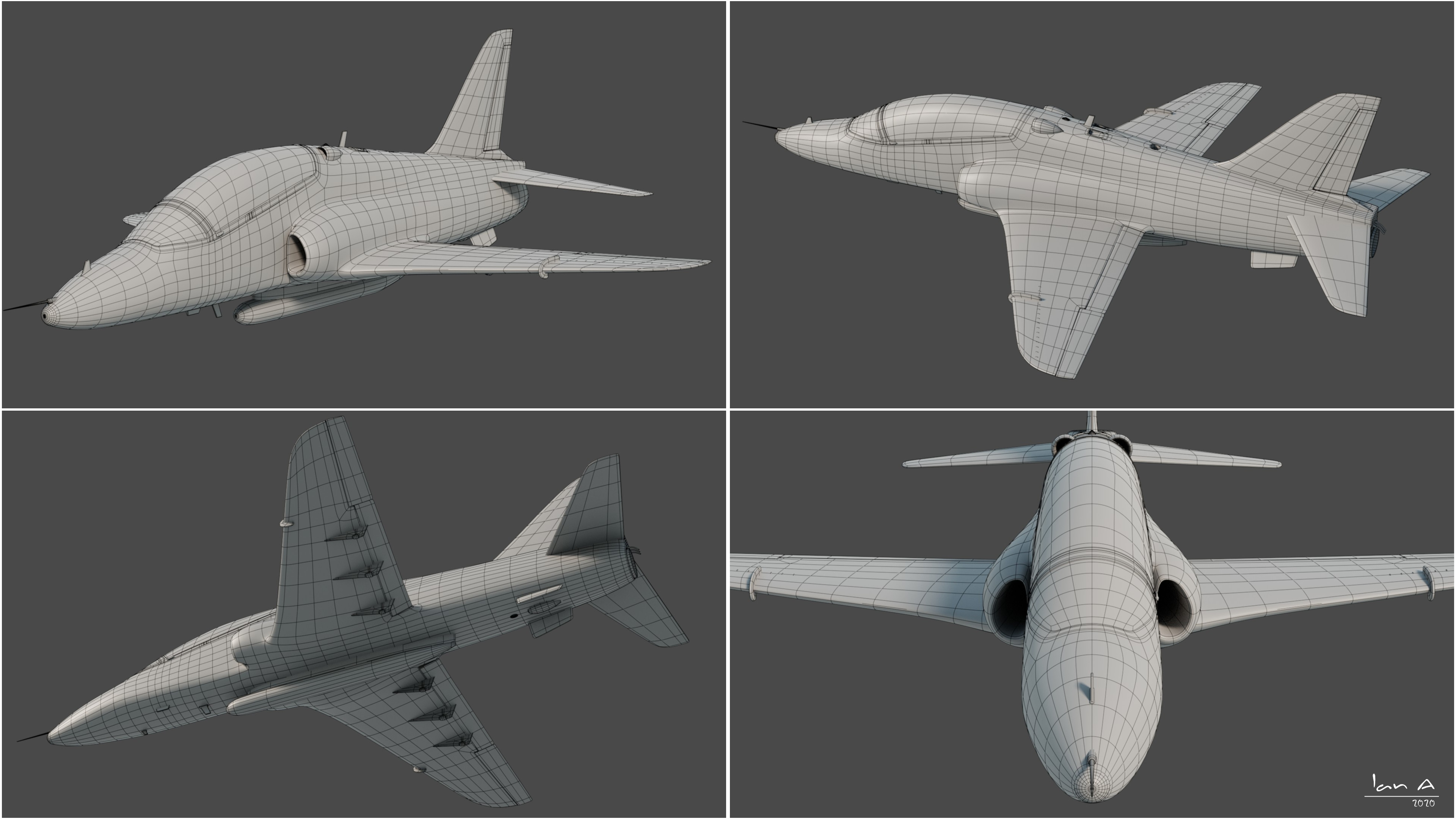
Yes very nice. Very clean mesh. And great render. If you don’t mind my asking, where did you learn how to add the white stripes to the mesh? My apologies in advance if this is inappropriate to ask this here… I’m rather new at this. Still nice work.
No worries - we’ve all been new at this at some point!
Can I just check what you mean by the ‘white stripes’? Do you mean the stripes on the livery / paint scheme of the aircraft? If so, it’s applied by a texture, as are the panel lines, rivets etc. There are lots of tutorials online about UV unwrapping and texturing. I generally do this sort of thing in Inkscape as it’s really easy to adjust without having to redraw anything from scratch each time.
That’s what I meant. At this point (little UV experience) I don’t understand how to get accurate lines or stripes on a mesh with the UV map. For me it seems very hit-and-miss to try and use a map for accuracy. I was hoping lines could be applied directly on a mesh layer with precise visual accuracy. I am used to working with 2D created art images (in Corel PhotoPaint) where I use bezier curves and pen lines to accentuate exact placement of features in real time, on the actual object; similar to line art only more mechanical. At times I try to move the lines of the mesh faces to get closer to what I want, but as you can guess this is not even close most of the time.
I have much to learn, or I may be expecting too much.
If there are any good tutorials, I would be interested. And again, nice job on your plane.
Iceless
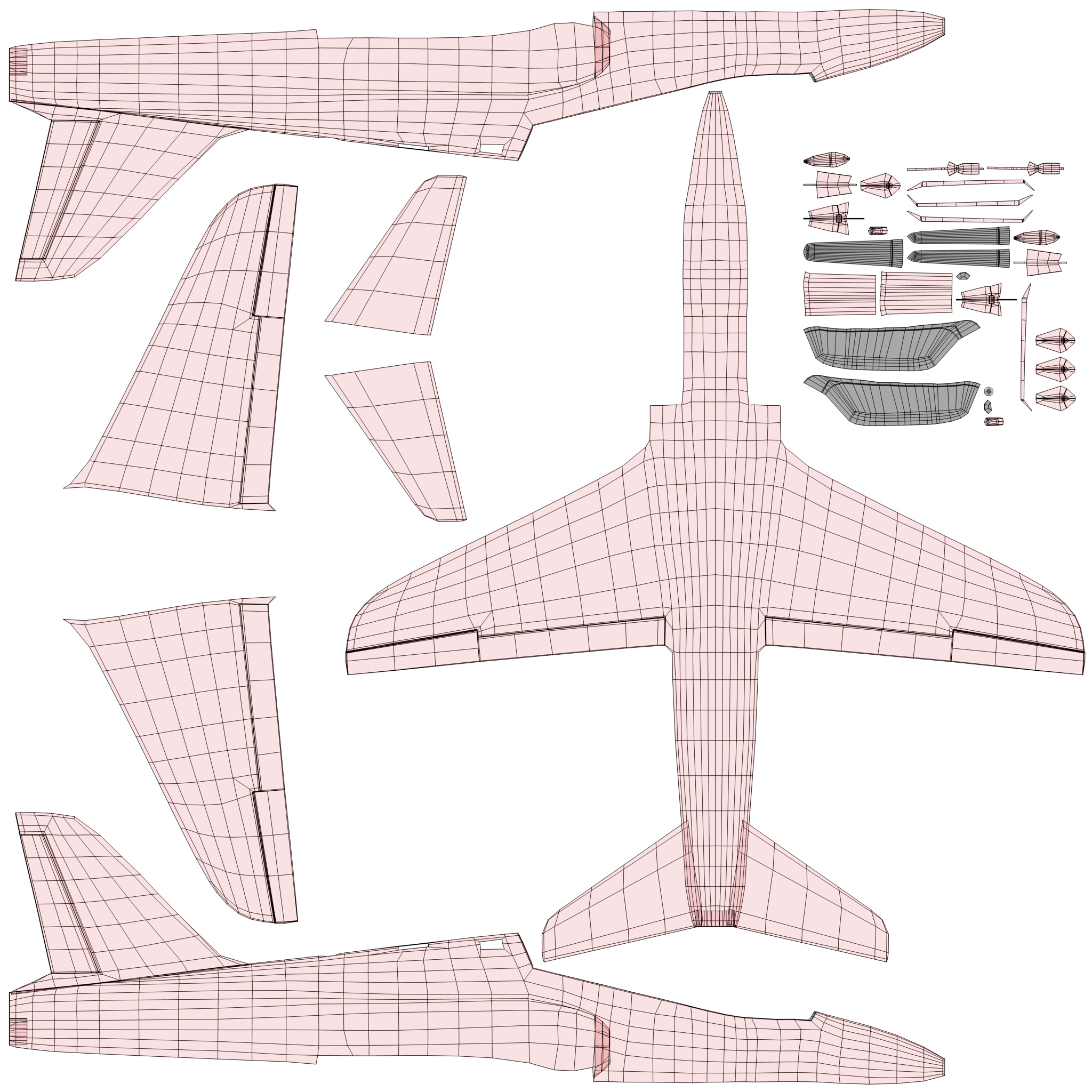
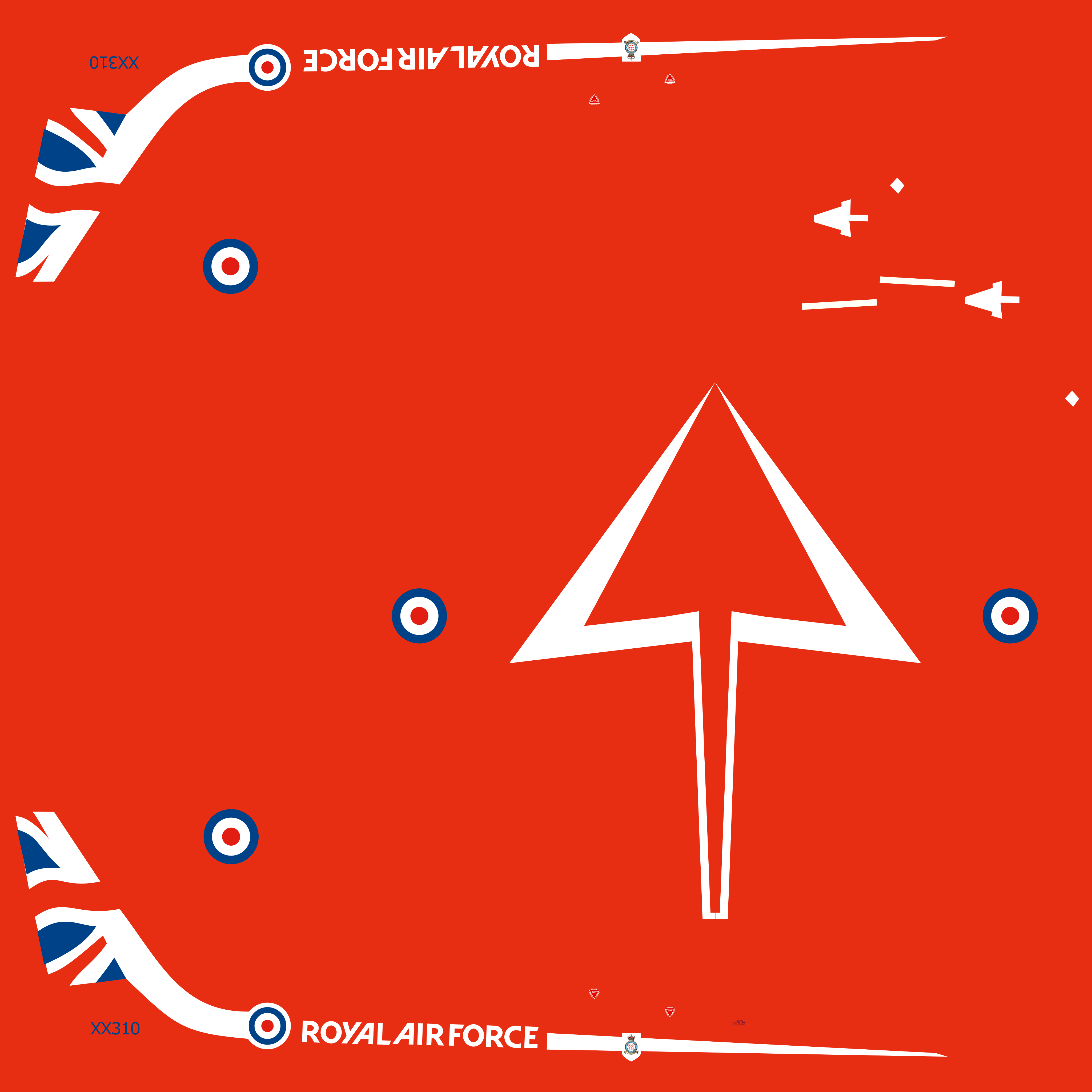
What I did was to use two UV different maps for the fuselage / wings object. There’s one that’s unwrapped in the normal way to get a fairly even UV map all around which I used for the grungy textures. I then added a separate UV map where I selected the right half of the fuselage, went into orthographic view, selected (for example) right side view and in the UV unwrap menu selected ‘project from view’. I then did the same with the other side, the top and bottom views, selecting only the bits of the mesh that you want to appear in each UV island before each unwrap. I then arranged them so they didn’t overlap and exported the UV map to Inkscape to do the colours. This is the UV map I ended up with using this technique:
…and, because it’s symmetrical I just needed to do most of the lines once and mirror them (though not the text, obviously). Then a bit of tweaking of the lines back in Inkscape once I’ve seen them on the model to make sure they’re in the right place (making sure you’ve applied the texture to the second UV map, of course). It’s quite mechanical and using curves in Inkscape so it sounds similar to what you’re used to.
Yes. That helps and explains what you did. I’m not sure if this will work for me, though. I’ll have to do some experimenting and see what I can accomplish. My intention is to create accent lines to bring out the dimension form on all sides of the object, and most of them will be connected and continuous throughout. It could be interesting. But then, what is life without a challenge?
Thank you for the answer !
I see. I am familiar with the unwrapping method you mentioned there. What I would like to know is how did you made that white stripe on the Diffuse Map.
it look really smooth and good lining. If you know a good tutorial that are very similar to what you did with Inkscape to do the color/diffuse. that would be appreciated.
It’s just using the bezier tool in Inkscape. From a quick search, this video covers the basics for that. The stripes and the flag on the rudder are just shapes drawn with bezier curves which you can bend into the shape you want. Stick them on a layer above a red background and job done.
@IanA
I am modelling on an F/A-18F for an open source game and wondered:
How do you go about cutting that canopy? Did you model one piece and cut it? Boolean modifiers? Or do you use a guide mesh to get such a nice topology?
Hi. I’ve never liked Boolean modifiers - I can never avoid annoying shading issues so I’ve never really used them. I basically did a combination of the two other things you mention. I did an initial model with the canopy and fuselage all in one object:
I then duplicated that and used it as a guide mesh, adding lots of subsurf levels to make it higher poly than my actual model. I could then separate the canopy into a separate object from the fuselage and add the extra geometry required to do the sharper corners and edges and used snapping or a shrinkwrap modifier to help me tidy up the topology while still keeping the initial shape.
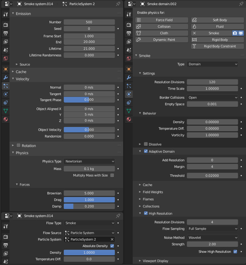
Great work! Thanks for the useful information I was curious about your smoke settings. I wanted to create a similar look for some flare decoys being dispensed.