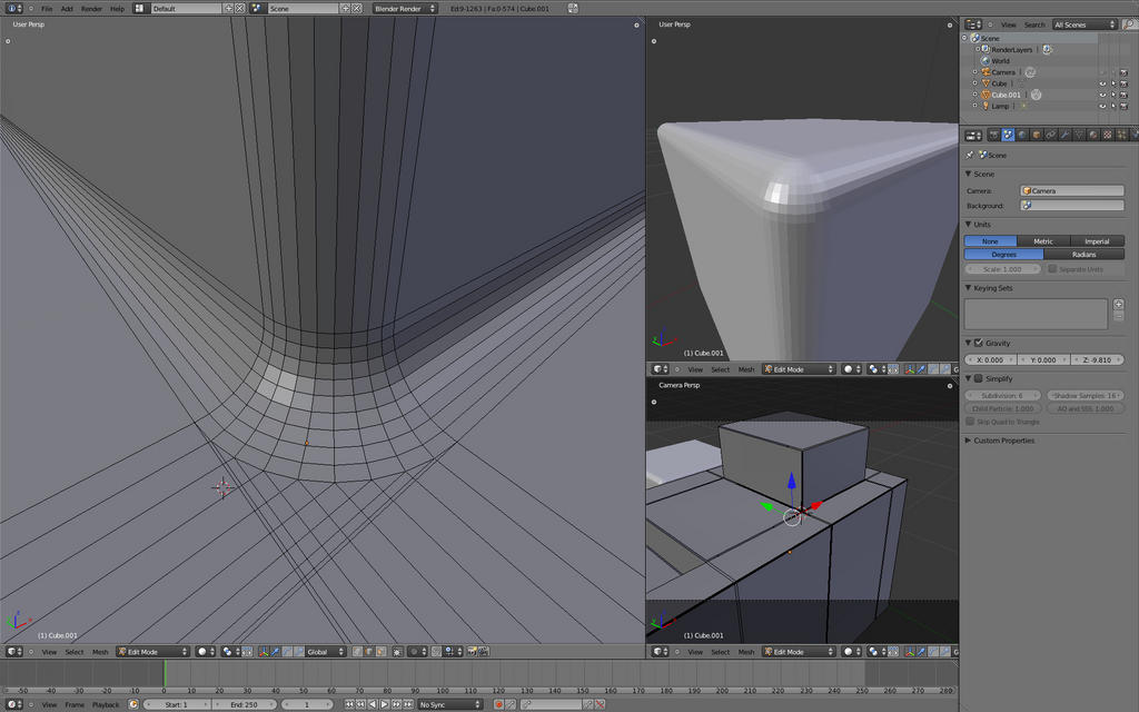
Bevel/Chamfer/Fillet in Blender 2.5 Is it a joke?

The amount of faces isn’t really an issue.
As long as it’s not like a lot of unused faces on a simple cube it’s ok. I don’t have to use low poly objects.
Your object is optimized to use as few faces as possible, but even from far away I would at least apply a bevel modifier, because you need the extra faces for highlights. (more realistic)

If you know how to model this object so it looks like the one from modo, please give me an example file. I do know that it is possible to use multiple loop cuts and I tried almost every possible way to chamfer an edge (at least it feels like that). The problem with loop cuts is the part where you try to bend them, so it looks like a rounded edge. I used the “proportional editing object mode” and moved the vertices down. Didn’t really work. The same with trying to rotate the faces in this mode. Didn’t work either.

Bezier curves work as long as you just want to extrude once to go from 2D to 3D. After that, you kind of have to convert to a mesh and then it gets really tricky to extrude faces to get the shape of my sample object. Rebogey found a way, but the mesh is almost unusable and needs a lot of additional work like melting double vertices, creating new faces or deleting unused ones. (but the idea is good)

Don’t get confused about the size of the object. I didn’t care for the scale, can be 1m or 100m. I just wanted to create an object so we can test different chamfer methods and compare them :slight_smile:

I use smooth if I want to fake geometry, so it looks like a smoother mesh, but it is not.
On very low poly objects smooth can look bad, but other than that I use smooth all the time (except to point out topology issues, etc. when the single faces should be visible)

I tried nurbs surfaces yesterday. Really interesting, but couldn’t find a good use for them yet. Can anyone think of a way to use them for this problem?

use your imported modo-object,
postition this cuboid to be in x-y-z-axis (it should already be?),
tab into edit-mode,
with Alt-RightMouseClick select near a vertices from those 5-10
close vertices-loops.
It will highlight in orange the whole loop-cut going around the whole
object.
You may try to scale this up or down (with key s and mouse-move)
you can see, there are a lot of those loop-cuts close together at
some special parts of the modo-object.

Now for creating such multiple loop-cuts in blender:
create a cube,
tab into edit-mode,
deselect selected vertices (press key “a”)
and over some edges press
ctrl-r, then appears the first loop-cut in the mid
of this mesh-part. Scroll up the mouse-wheel
and there will be more, maybe go for 3 … or 5.
Then press left-mouse-key and those will be created.
With the fresh created loop-cuts still selected (highlighted)
press key “s” to scale all, but only for one axis-direction.
Press x,y or z for the appropriate direction and when you
now scale all along this axis, they are coming closer together.
If they are close enough (like the modo-object), then
move them to the left or right of the cube-edges.
For your sample modo-object, if you dont go for this
special low-poly sample of mine, you would create loop-cuts
to have the faces on the cube to extrude out and one part in.
So it is not much more work, when you create one loop-cut
or multiple loop-cuts at those parts. This works easy in rectangular objects
(moving those loop-cuts along the x,y or z-axis is easy and wont disturb
the geometry - like in the modo-object)

I hope the explanation is easy to understand …?

I’m not quite sure what you just described. You basically explained how to make this object without chamfered edges, haven’t you?
I know how to get the basic cube. You added several loop cuts, so what did you do with them? From what I understand I end up with the object with several loop cuts, but without the chamfered edges?!

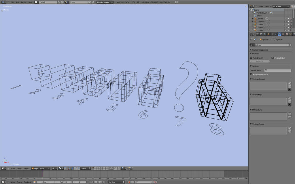
I added 2 screenshots. One shows the steps to create the object, where the part I don’t know is missing, the other one shows the modo object without chamfered edges, just a lot of loop cuts.
I thought I can somehow make the round edges myself, but everything failed so far.

PS: you actually can move the loop cuts around on the modo object, you only have to be careful to select the whole edge and not only single vertices or loops. I moved them for the second screenshots. :wink:

Attachments


@DiLer:
at the steps 3,4,5
you create not only 1 loopcut,
you create on the left and right side
of each those loopcuts another loopcut.
Or instead of only one, create 3 loopcuts (scroll up mouse-wheel)
and scale all 3 along the correct x/y/z-axis close together.
Next, what is totally missing, you need to create loopcuts for the
edges too, not only for those parts where you want to extrude the faces
later.
And last you will need a loopcut for the extruded faces. To extrude the
faces you have to select the middle face and the border of faces of one
loopcut around it - you extrude 9 connected faces, big one and surrounding
8 small ones.
You dont need to go for 5 loopcuts at every edge like the modo-sample.
To tweak the sharpness/rounding of the subsurf-modifier one additional
loopcut at each side of an edge is enough.

For a symmetrical object (like yours) you would only create one half -
one half with the extrusion, then duplicate/mirror it and move the extruded
part into the inside. After duplicate/mirror, if you dont want to bridge with
faces both parts, you can use a an additional loopcut in the mid to join both
parts.

Then you might only need a subdivision modifier or a combination of one bevel and a subdiv-modifier (depends on the resolution you want)

To check the result of such loop-cuts:
use a simple cube,
add ony a subdiv-modifier with view=2, render=2, catmull-clark
then add one loop-cut after the other to every edge
and watch the changes. You may only do this for
the edges of one side to compare the result with
the other side. Then slide those loop-cuts closer
to the edges - and watch the sharpness.

Then you may add a bevel-modifier at first place in the
modifier-stack and reduce(or not) the subdiv-modifer to view=1, render=1.

Next check the differences when using a subdiv-modifer with simple instead
of catmull-clark (its a bit like a bevel-modifier).

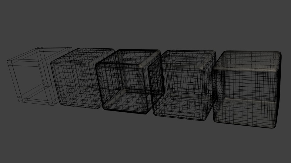
Update/edit: i appended a picture,
its one cube with loop-cuts for every edge
the first cube is only the cube with the loop-cuts, they are not
too close to the edges to display the effect.

second cube is only with a subdiv-modifer view=2,render=2,catmull-clark

third cube is 1.Bevel with 0.1 width and 2.modifer same subdiv-mod like above

forth cube is 1.Subdiv-modifer like above and 2.modifer is the Bevel like above

fifth cube is 1.Subdiv-mod like above and 2.modifer is Suvdiv with view=1,render=1,simple (instead of catmull)

There are more combinations and at last there is a big difference with
“flat” or “smooth” objects - this was only with “flat” setting ? might be better
for architectual, etc. objects (not organic ones).

Any suggestions for a better display of those different options?

ps. and dont forget to select a loop-cut of vertices in edit mode
use the Alt-RightMouseClick …

Attachments


Thanks for all the informationen, but I already knew that :wink: It’s what I posted in the first post.
It’s the subsurf-modifier method (optional with bevel).

I used more loop cuts on the first screenshot of my last post. It’s like the modo object but without the chamfered edges.
You added a subsurf modifier to get them, which gives me this object with a lot of unused faces that I have to delete by hand or just live with it (will be a problem later).

Like the last cube on your screenshot, the one on the right. That looks like something around 3000 faces. I think subsurf and bevel together doesn’t really work. The bevel modifier seems to destroy the topology after a while.

I wouldn’t use mirror for such simple object, but you gave me an idea. What about creating only one perfect corner, like making a standard cube, give it a subsurf modifier with 4 or 5 subdivision. Then delete everything except one corner.
This corner than can be reused, to create whatever you want. Just image the final object you want to model and duplicate the corner to get more of them. You then would have to rotate the corners and set them in place. After each corner is on its position just connect the vertices to get one object.
Maybe it’s even possible to get all the vertices of the corners in one vertex group, so you can scale them all by once, making it possible to change the size of the chamfered edges?! (they will probably scale to the middle of the object though)

Don’t have time right now, but maybe I can check that out later. If it works I post a file or screenshots.
I hope I explained it so it’s easy to understand. It’s a simple idea, but hard to describe.

Another thought of mine was to make the “deleting all unused faces”-part a little faster by selecting these unused faces all at once. With shift+G you can select similar things. Didn’t really worked for me though. Maybe someone has an idea how to use this to fasten things up?

@DiLer:
the problem is, i still dont understand for what kind of edges-rounding
you are going?

And shure it is possible to cleanup such a mesh.

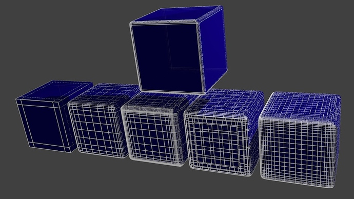
Here the same pic, with wireframe rendering
and a 6.cube above the row of the 5 cubes with/out the modifiers.

For the 6.cube i applied the 2 modifiers of the last cube-sample
and deleted most of the loop-cuts - the inner ones not really necessary
for the flat faces.

The point is: all five cubes in the row have only 54 vertices, its the modifiers
to make them high-poly. I dont know why someone would go for a subdiv-modifier
of level 4… 5… or like you said level-6? Do you wanna sculpt those things like chairs, tables …?

The 6.cube above the row of cubes has only 292 vertices and one could delete
more un-necessary loop-cuts - but the last questions is: what kind of corner/edge-rounding you want?

You should check the other combinations to get your wanted lookout.

Attachments


Sounds like you want more accurate bevel. Well then you can make it with spin tool. Here I set the cube up with mirror modifier to minimize the number of creation steps. Cut away the corners at same dimension as the radius; cut and locate with Transform property. Locate the center of bevel from one of the corner vertex; just extrude the vertex with same dimension as radius.

http://i1135.photobucket.com/albums/m626/cabby24/Blender%20Pics%202011/rounding1.png

Snap the 3D curser there. All 3 edges can be span from this center.

http://i1135.photobucket.com/albums/m626/cabby24/Blender%20Pics%202011/rounding2.png

Even the corner can be span from this center.

http://i1135.photobucket.com/albums/m626/cabby24/Blender%20Pics%202011/rounding3.png

Very clever technique with the spin function !

at ridix
Nice method, but took me some time to get the hang of it. Looks clean though and I like the fact that you can determine how many faces you want. But can you imaging doing this for a whole complex object? It might probably be faster to use the subsurf method and delete loop cuts. Don’t know. (problem there is that Blender sometimes crashes)
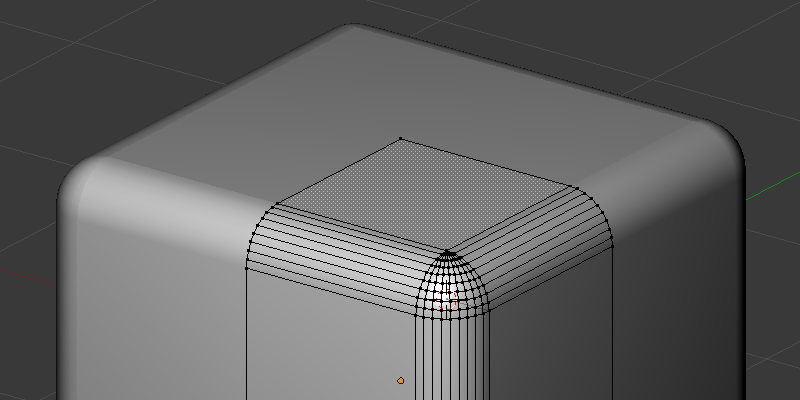
Beside the time, the edge from the extruded face (the vertex pole) is a big problem. I attached a screenshot how I did it, but that really took some time. I don’t really want to do that for every edge on a object ^^
How would you do that?

at test-dr
You can see what result I want from my first post. The link under “Subdivision modifier and deleting unused edges”. That’s pretty much what I want in the end, probably some more faces for the edge, but all in all something like this. A really small rounded edge, mostly to get some highlights. As I said I mostly want to model a kitchen right now. I like that black and white shiny modern kitchen look. (wouldn’t hurt to find a method that works with every object though g).

I used more subdivisions to get more faces on the edge, which gives nicer edges, but also more unused faces you have to delete.

And in the end it doesn’t make any difference if the modifier makes the object high poly, or the object itself is high poly. (at least not that I know of)
Nice thing about modifier is, that you can turn them off or down to make work easier.

Maybe offtopic:
Things I just found out about Blender:
The metric system sucks? Can I somehow use a snap tool with a grid of 1cm, or 1mm instead of 1m? The sliders are pretty much useless, because they react with m too. For example the transform information, where you can see the exact position of a vertex. It just shows km, m or cm. If you type in 0.01cm it jumps to 99.987µm…lol? And with 0.001cm it directly jumps to 0m and weird things happen.
The bevel modifier does something similar, but at least you can type in 0.001cm etc.

Another thing: If you scale your object only in one or two directions, you can’t bevel it anymore, because the bevel modifier also gets stretched. You have to grab and move the faces, or vertices, etc. Only happens in object mode? Caught me by surprise, had to delete the object, but just started anyway. I thought only 3ds max had problems with scaling (manual pretty much says to never ever use it^^)

Attachments