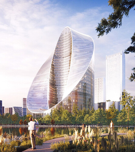
BIG (Bjarke Ingels Group) is one of the top world class architecture firms today and they just published renderings for a truly amazing project they are currently working on. The plan shape is very simple (a cylindrical floor plan) which has been sculpted so that the majority of residents facing the interior courtyard still have more expansive views. The final shape however looks complex and hard to do. BIG’s “Infinity Loop” (nice name as usual) looks so cool I wondered if I could do a quick Blender mass model just to figure out what/how they did it. I started out with a “thick pipe shape” and then tried several complicated mass “Loop cuts” which seemed really complex and did not work quite right. Finally I realized that what they did was actually quite simple.
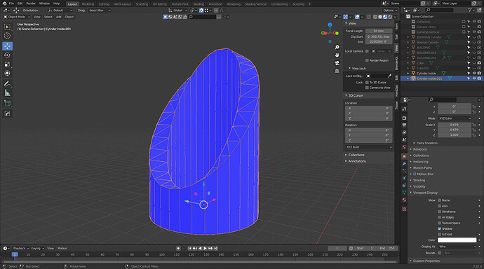
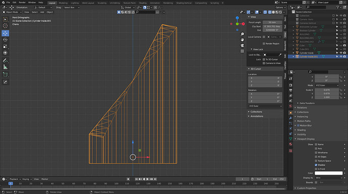
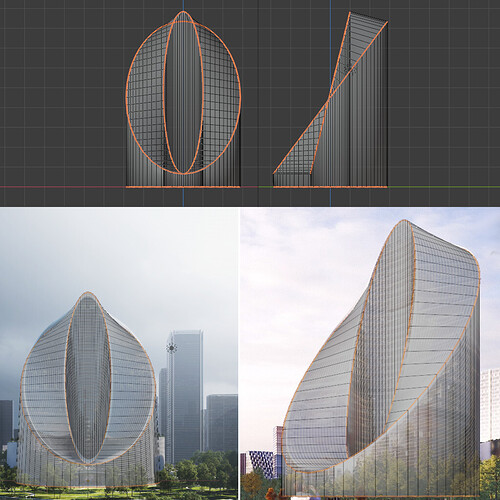
I am attaching screencopy views, the solid view shows I managed a quick massing +/- very like theirs and the wire views show how they did it. I modeled two concentric unconnected open ended cylinders, the larger one to become the exterior face and the smaller one to become the courtyard facing face. Basically the exterior skin of the building is then Bool cut in a straight angled line; the “interior” courtyard face is then cut in a slightly different angle so the top and bottom cuts of both are more or less at the same height. Then both cut top edges are connected with “Bridge Edge Loops” which gives you the seemingly complex but very cool massing. The rest is of course fairly laborious but straightforward. This is no complicated Zaha Hadid organic tesselation, BIG’s complex looking simplicity is, well, genius.
If any of you want to see the remaining renderings by BIG you can find them here:
Bjarke Ingels Group to Design Mega-Sustainable Infinity Loop on the Hangzhou Horizon | ArchDaily


