No idea lol I know that from seeing a post here several months ago in which someone asked how to change the speed of an object on a curve… Atom told them how to ctrl+LMB to add in points in the IPO (which you couldn’t seem to do otherwise). I figured the controls would be the same in 2.5 and it turns out they are
Thanks, cause that is a great tip to know. From what I have seen, but I just started today, the graph editor looks to be a great tool indeed. The CTRL+LMB was the only thing I was missing, not that it is really needed with all the upgrades. However, I can see places where creating and controlling curves can be beneficial. It’s nice to know that I can still have that ‘low level’ control…
So now, my only bitch with 2.52 is that my monitor is too small to fit everything I need on screen in a clean way…:spin:
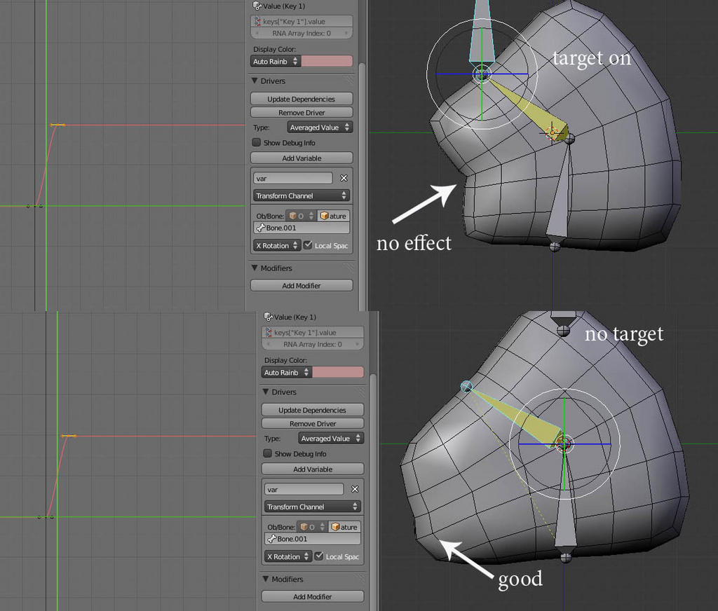
I think I’ve got it set up the same way, but it’s still not working like I expect it’s supposed to. Translating the control bone in any direction drives the value up, regardless of proximity to the target.
bunny:
I’m guessing that for the behaviour you want, you should:
Disable the ‘local space’ options on the bones. In this case, they are just using their locations relative to their rest-pose locations, so this is not that useful to enable.
Tweak the generator curves so that the equation formed by the number boxes in the panel look like 1.0 + -1.0 x
The second tweak is needed because the starting distance of the control is always 1.0 units away from the relevant target(s) rather than being 0.0 units away. I can explain this in more detail as to how I got this later if you want (or I’ll edit this post later, but no time now…)
Aligorith:
That worked, thanks! I think I’ve sort of got the gist, but definitely would appreciate hearing how this works in some more detail whenever you get a chance.
Firstly, I took a look at how the distance of the controller from the relevant indicator was, and how this related to the strength of the shapekeys.
–> when the controller is at it’s default position (0,0,0) local:
distance has maximum value, while shapekey should have zero influence
–> when the controller is at one of the indicators:
distance has minimum value (i.e. should get to 0), while shapekey should have total influence
Alright, from this, we can work out that we should have a negative sloped relationship between the two (i.e. with distance as x value, and shapekey influence as y, see above, and draw out on paper if you get confused).
As for the ‘magnitude’ of this slope: this can be worked out using 1/distance, where distance is the distance from the controller’s default position to one of the indicators. To find this distance, you can turn on the ‘debug info’ for the drivers, and have a look at the value returned by the ‘Distance’ driver variables that you’ve got.
Finally, for the first value of the generator, that is simply the maximum shapekey influence that you want to have applied. Check step 1 again if you aren’t sure
I’m still struggling with drivers and shape keys.
If I have a simple IK chain I can’t make the shape key work with the rotation of a bone, but if I disconnect the IK target the shape key works.
Here’s my test:
I’ve been looking for some good tutorials on how to use drivers in blender 2.5. In fact, I’ve found some! The thing is: they are all beeing used on shapekey- or constraintsvalues. It should be easy to, for example, generate a driver to control the color of an object. Following the steps on the tutorials for shapekeys or contraints just doens’t work. I won’t even get the error when adding a variable. My question simply is: “How do I add a driver to control the RGB-values of a material?”.
KingJordi:
Unfortunately, apart from data directly related to objects, drivers are currently not handled by the dependency graph correctly, and will fail to update. Hence, nobody has any tips to share on how to do this.
If you’re really determined to do this though, here’s what you could do:
Go to the Outliner, and change its mode to ‘Datablocks’
Find the ‘Objects’ entry and expand it
Find the name of the relevant Object and expand that
Find the ‘Material Slots’ entry for the Object, and expand that and the material associated with it (twice)
Find the ‘Textures’ entry under the innermost material you just expanded
Under the texture, find the relevant properties you wish to add drivers to
Select these by clicking in the empty space beside the entry, so that the entire row is now a light shade of blue
Press DKEY
You should now have some drivers added to play with. This process can also be used to add drivers for material settings, or for other purposes such as adding Keying Set paths, etc.
Thanks for your swift reply. It actually does the trick! I guess that in these datablocks, the data I find, is directly related to my object while the data in the properties window is more like a pointer to the actual data…
Everything works fine if I follow Aligorith’s steps. Now I tried the same thing (just changing the color by a driver) in GLSL textured mode and IT WON’T UPDATE . So the question is: Is this still something that has to be fixed or is there an ingenious solution to my problem?
I have created an example .blend file with the regular cube and another mesh which is acting as a driver. If you move the mesh over the z-axis, the cube turns blue, moving it over the y-axis will turn it green and moving it over x-axis turns the cube red. This works perfectly fine in the solid shaded-mode and even in textured shaded-mode. But when I change the shading method to GLSL in the display tab of the properties window, I don’t get a live update? :spin: I’m guessing that this still has to be implemented, but my question is:
Is there a way to get my cube to change color using a driver in GLSL textured mode?
GLSL mode has a number of update bugs. Last time I checked, even simply moving certain lights sometimes didn’t trigger any updates. The best way to get the GLSL bugs fixed is to report them in the bugtracker.
Hey guys, another question, if I manually create a curve, how do I set the location of the control points?
Like before In 2.49, I should have a curve with Xmin=-0.16, Xmax=0, Ymin=0, Ymax=1. I can get one point(X=0, Y=1) correct by changing the cursor and snapping the control point to the cursor, but the value -0.16 can’t be reached? even if I try to move the point to it without snapping, it just “jumps over” a whole range on the timeline.


 . So the question is: Is this still something that has to be fixed or is there an ingenious solution to my problem?