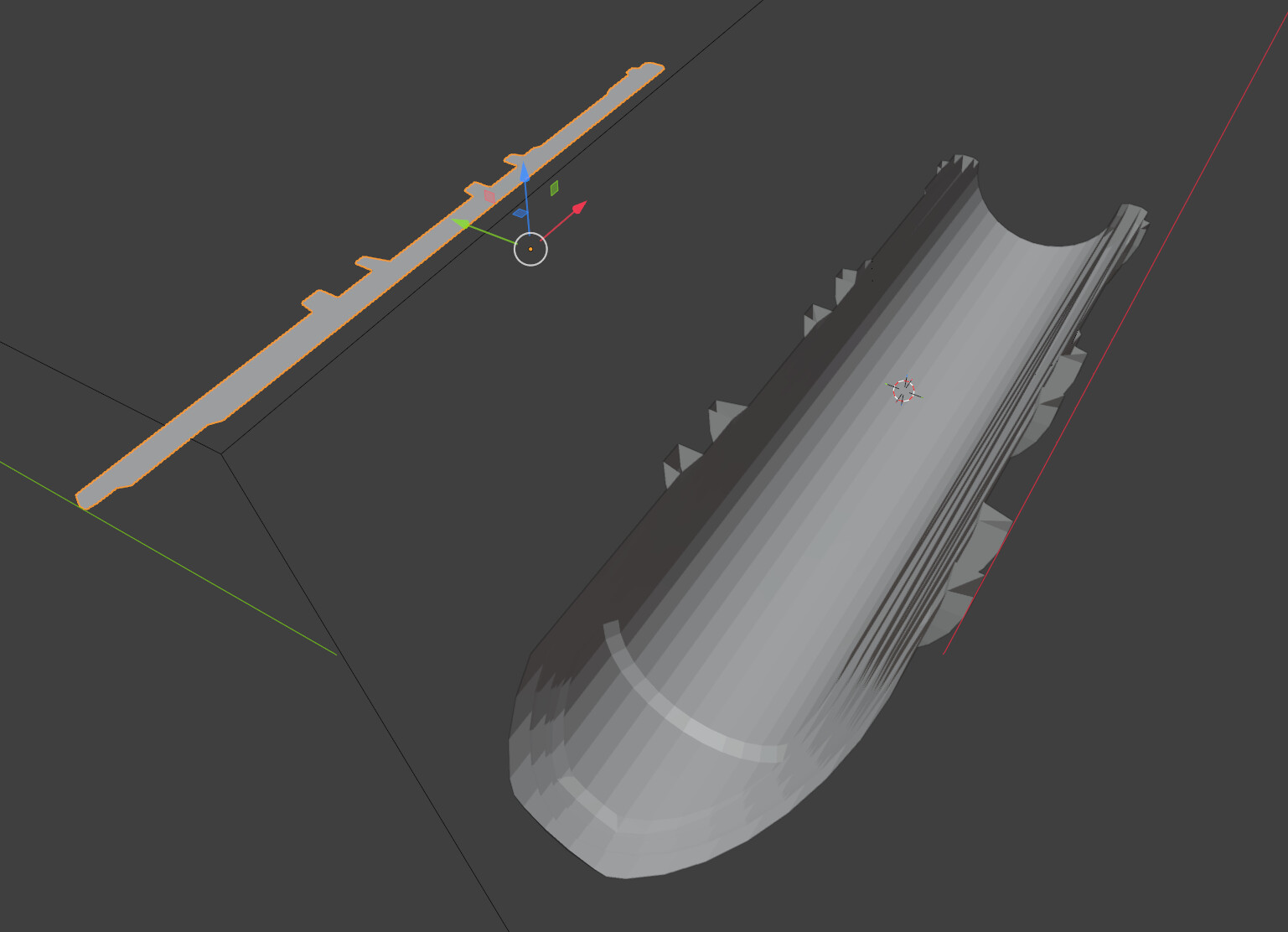
The Spin tool in Blender automatically uses the current 3D viewport’s viewing angle as the pivot axis.
Why? That’s terrible.
Re-editing Later: You cannot edit these parameters once applied…
That’s even more terrible, why isn’t that tool parametric?
The Screw modifier rotates all the polygon edges, creating tons more geometry than is necessary and destroys the flat plane of my cross section shape… what good is this?
Blender’s lack of a decent simple lathe tool was something that really suprised me, when I started using it. Fortunately, it’s not the only option one has to get that sort of thing done.
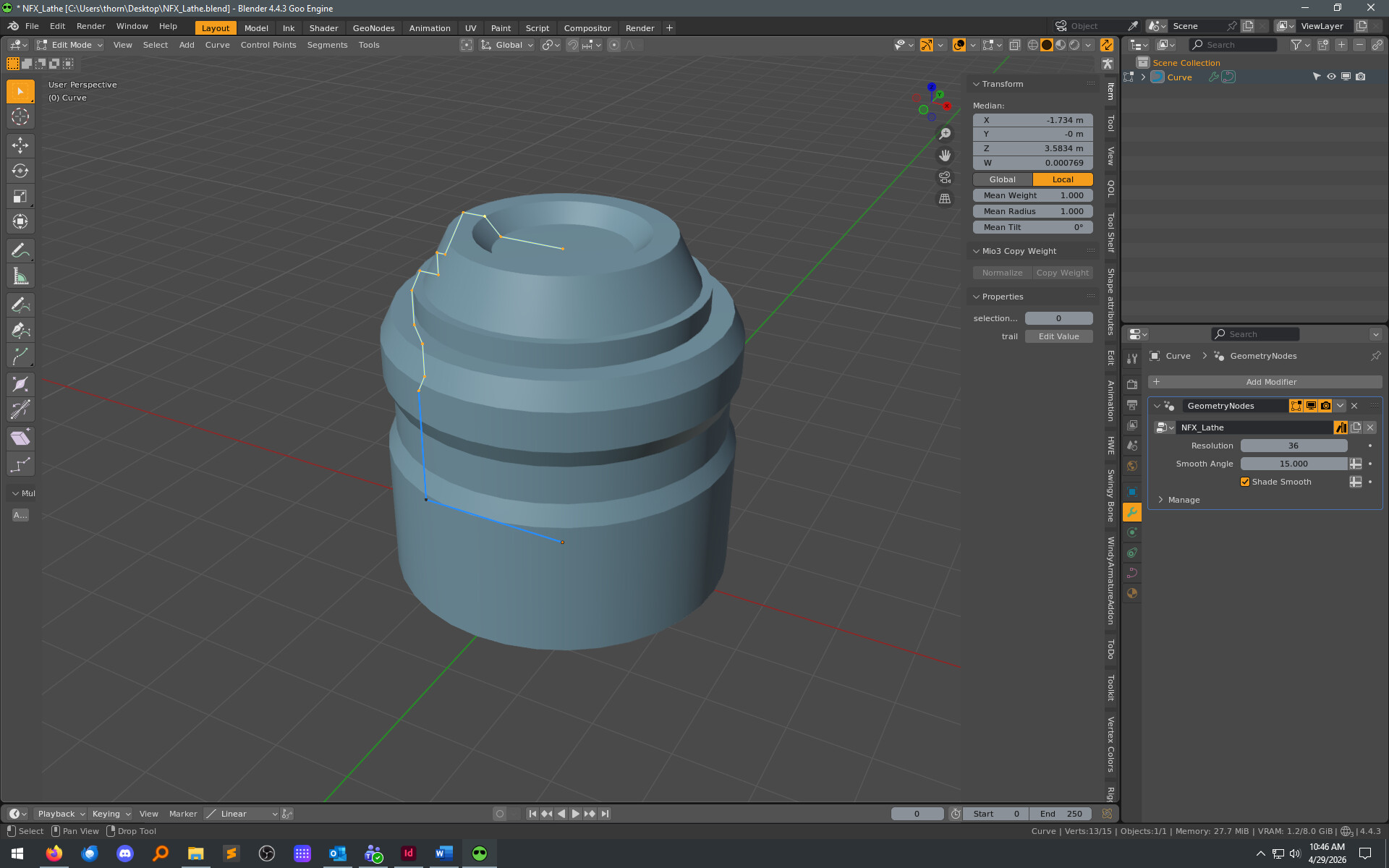
Here’s a geonode setup I made, which works well in many cases. (And, it’s pretty simple to understand how the nodes work, and to modify if needed.) Just make your curve, and put the modifier on it. Adjust your curve after, if you like.
Spin operator, from Extrude menu in edit mode, is indeed an old operator, that is view dependent.
Several old operators were created to be used in a sequence, using numpad keys to jump to standard views, to orbit or to align view to selected element.
Using by default, a view axis, was a way to limit complexity of code of the tool, to keep them small, and to keep size of the whole application small.
The same way, this tool uses 3D cursor for center of rotation.
If you take a look to View > Viewpoint, Navigation, Align View menus, you will see that a lot of shortcuts are related to numpad.
At that time, there was no gizmo to navigate in viewport ; user was forced to use those shortcuts.
And principle for operators, at that time, was to tweak settings, before validating the action.
So, the operator is older than panel to adjust last operation.
Nowadays, you can use Spin active tool, from toolbar, with a gizmo using default chosen transform orientation, and totally neglect viewpoint.
You can use array modifier to duplicate the whole mesh, with same kind of gizmo.
Most of modifiers from Generate category are unable to handle a selection by a vertex group. Only recent ones can. The ones created just before implementation of Geometry Nodes. All of them have been supplanted by Geometry Nodes, for parametric purposes.
You can create a Geometry Node modifier or a Geometry Node tool, to duplicate a selection of mesh components.
I find it curious that it would be expected that the spin tool would work with a mesh that already has a polygon.
Don’t get me wrong, I’ve not used everything out there - but going back as far as Infini-D in 1996, a line segment only was the expected ingredient for a spin/lathe tool.
Delete the face first, keeping the edges, and in the Screw modifier, make sure to set the desired number of View/Render Steps (EDIT), and for added control use an empty to manage the point of rotation - happy accidents can occur there.
The Spin tool can be used to create circular arrays, too, by enabling Use Duplicates option.
The Screw operator will fail and show an error message, if selection is not only made of edges.
It is obvious to anybody trying Screw modifier, that using it on a mesh with faces does not give expected result.
It is a modifier available, for Curve type.
But, in Blender, tracing of path from one vertex extruded, through Extrude at Cursor operator in Mesh Edit mode, may be relatively easier, more straight forward, than using a Curve object to convert into a mesh, later.
Yeah, the object is a curve object, that Screw mod did some weird stuff, all these workarounds seem completely unneeded for some a basic 3D operation… thanks!
I tried that, it seems to have worked, but the screw mod does not cap the ends and the result does not respond to autosmooth, it has to be collapsed into a mesh first which removes the parametric editing… I have to convert it to mesh, then select the edge loops of both edges (180 degree screw, for a cross section…) and fill them.
All just for what would be a simple lathe process in other programs… I come from a C4D background.
I also come from a C4D background, so I can totally relate to the workflow you’re trying to use here. Maxon’s modifiers (well, the ones i remember) really are done in an easy, elegant way.
Also, you’re quite welcome.
(Hint: That node setup includes a value in there for dealing with overlapping points / merging. If you apply the modifier and it decimates something badly, just open the geonode up and increase the merge distance a bit. It’s not all perfect, but I was shooting more for “close enough for most of my personal cases” than "works all the time, zero issues.)
BTW - for a lot of killer premade node setups, look up Higgsas on this forum. Great stuff.
The Screw modifier should act as a lathe, if default Screw value is kept (set at 0), if one extremity of profile path is aligned on object’s origin. If it is not the case, an empty can be used to replace origin, to define other axis than local axis.
The Screw modifier has a Merge option to weld duplicates of extremities aligned with origin, on axis of revolution.
The Shade Auto Smooth operator should add a Smooth by Angle modifier pinned as last one. The Screw modifier can not take into account Sharp Edges, marked in Edit Mode. The attribute is not interpolated. But the angle value of Smooth by Angle modifier should have an effect.
SVG are often images with infills corresponding to a certain color.
Strokes in imported SVG should be imported as closed curves without filling.
But Infills are imported as filled closed curves.
Each curve being a separate 3D object curve.
You can simply change Fill mode, in Shape panel of Curve properties.