Before I start I would like to thank u/Baldric for posting what I based this on here. Since not all of his node groups were exposed I decided to give a shot myself. I will be writing an in-depth explanation of how it works and how to recreate it.
Here is the .blend
TLDR at the bottom
Here are some variations made with the final node group.
1. Understanding Vectors in Blender
This method of creating scratches manipulates the vector from the object coordinate to repeat a wave texture across an object. Vectors are just of way of telling blender where to map what part of the texture. For example, a gradient texture is told by its vector to draw its center at (0,0,0) and its end at (0,1,0) and (1,0,0).
The vectors provided by the texture coordinate node are just combinations of x, y, and z, locations for a texture to mapped on to. On a 2d plane, the generated coordinates go from 0 to 1 on each axis.
However, the object coordinates go from -1 to 1 on each axis.

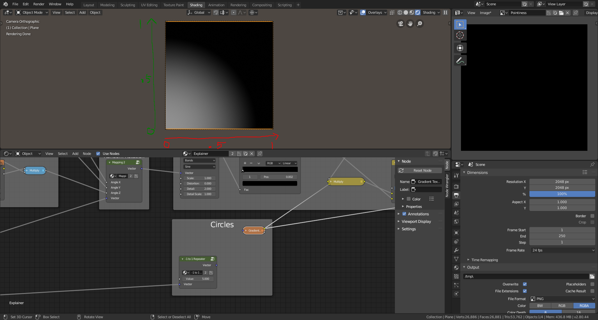
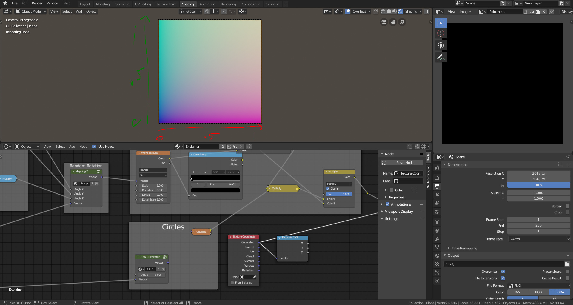
When we separate the generated coordinates into x and y it is easy to see how the texture coordinates are formed. The X channel goes from 0 to 1 and so does the y and when they combine using a combine xyz node we get our original coordinates back.
X-Coordinates
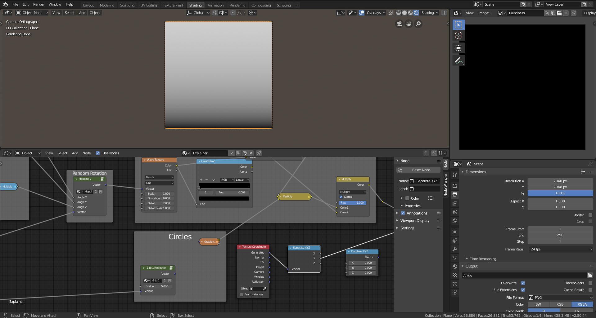
Y-Coordinates
2. Creating a texture coordinate repeater
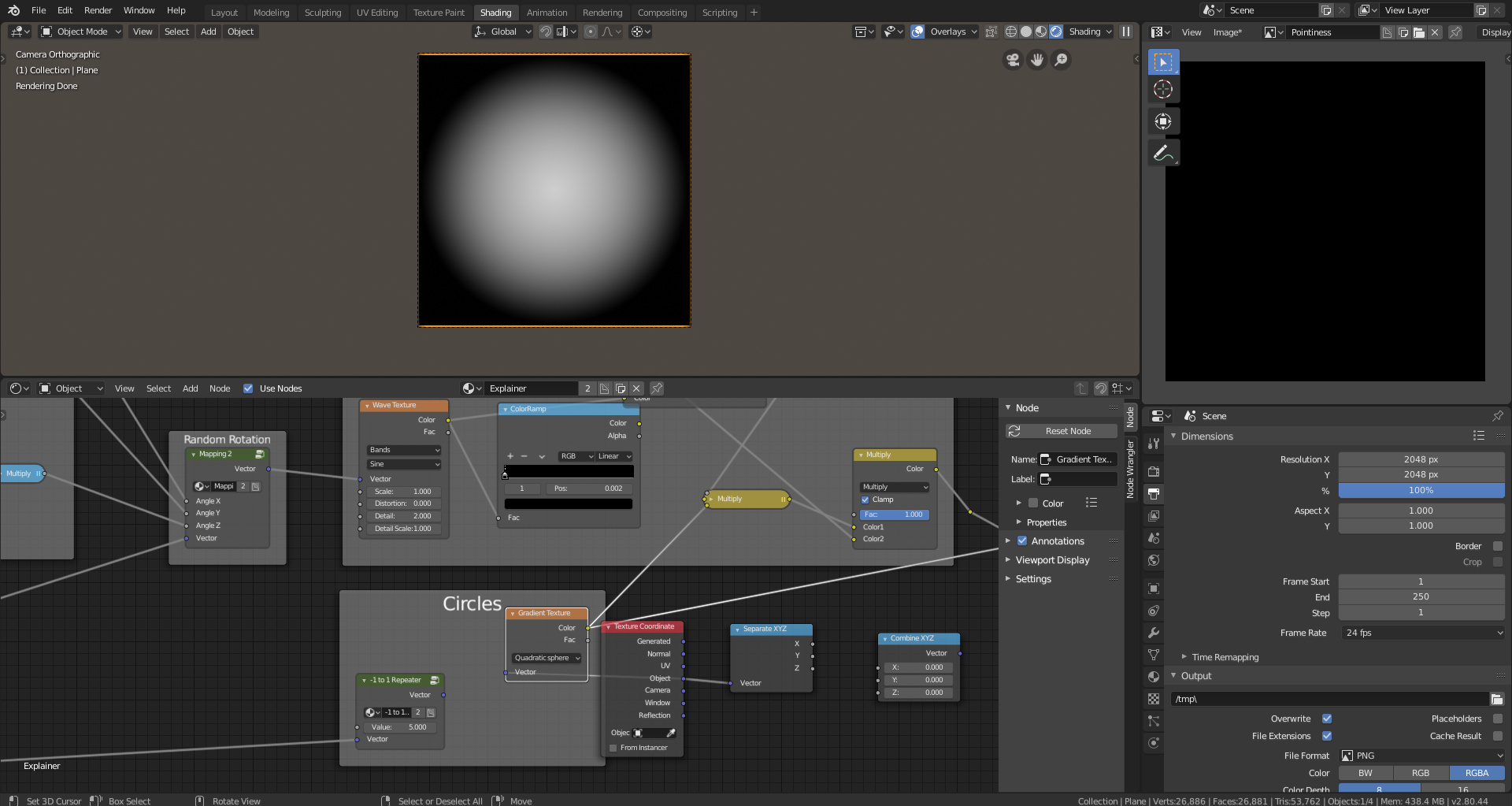
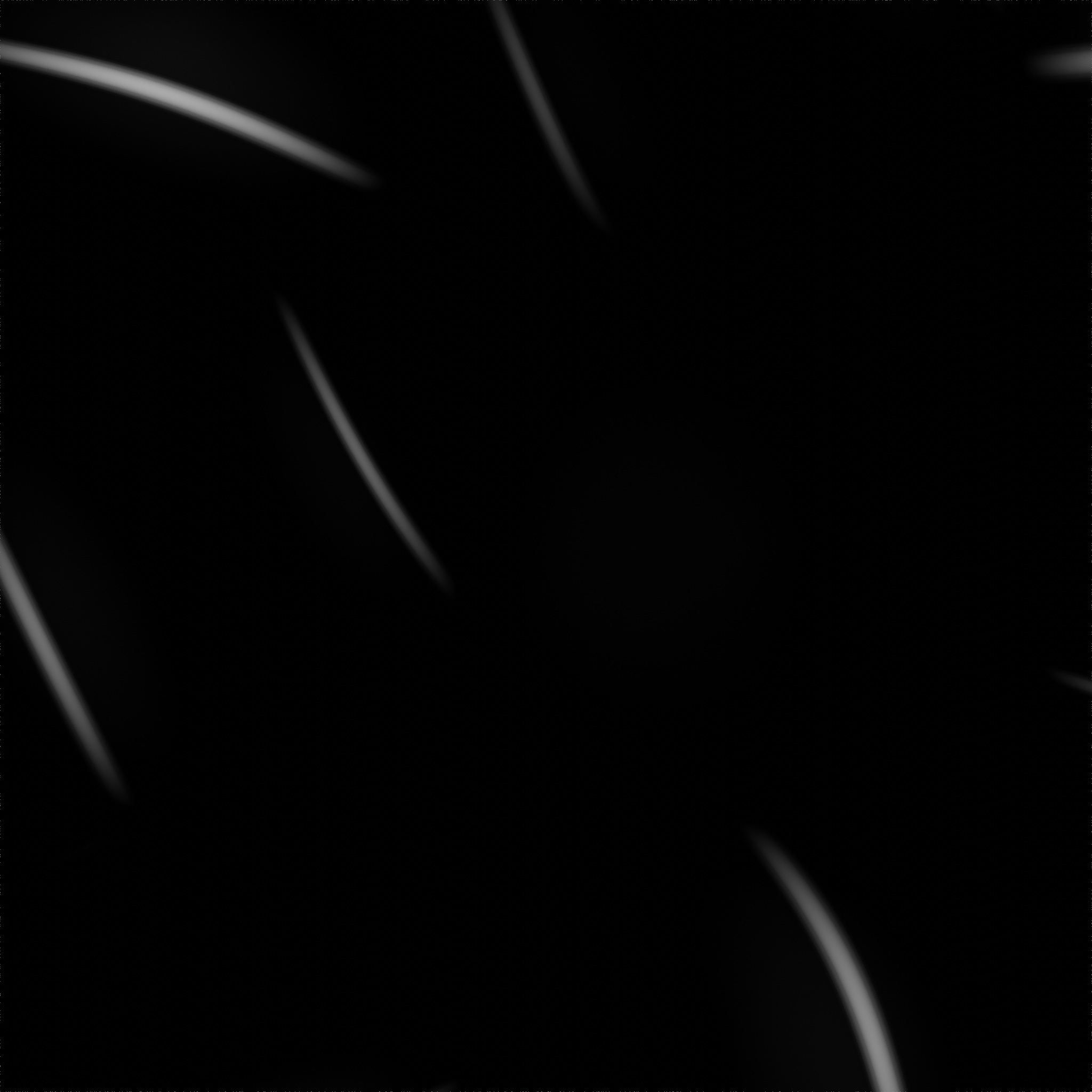
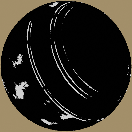
Spherical Gradient with Object Coordinates
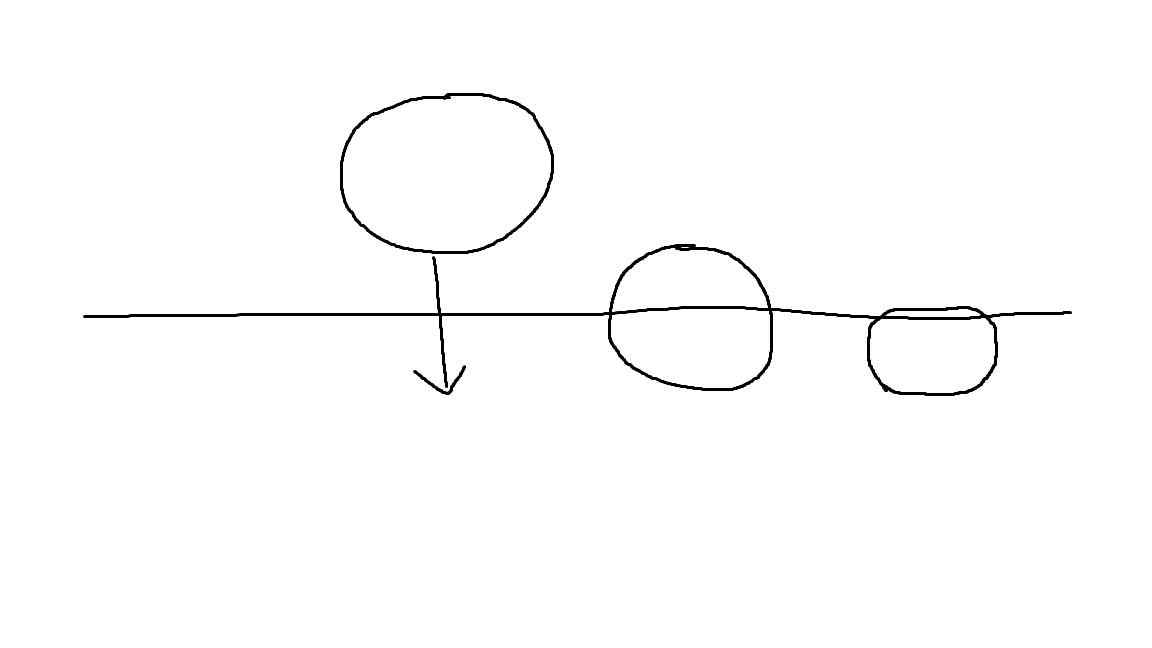
Using this knowledge we want to take a spherical gradient, which is mapped from -1 to 1, and repeat it across our mesh. To do this we can make our texture coordinates repeat -1 to 1.
<[-1_-.5_0_.5_1][-1_-.5_0_.5_1][-1_-.5_0_.5_1]>
On a number line, this is what we would want. To achieve this we can use blenders math nodes.
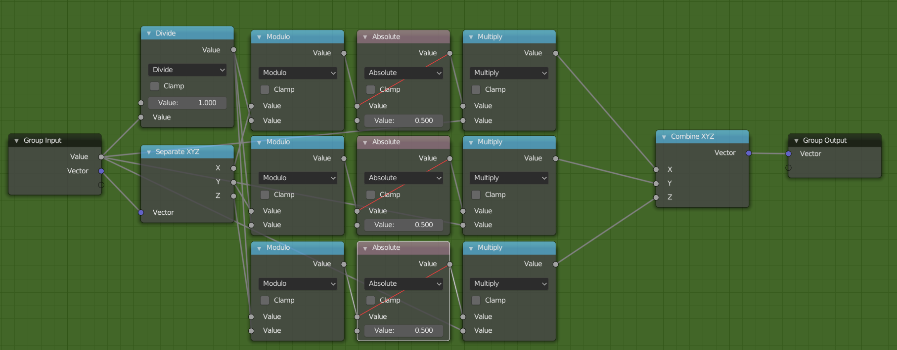
Final -1 to 1 Repeater
Our final group node that repeats our texture coordinates will look like this. Let’s break it down step by step.
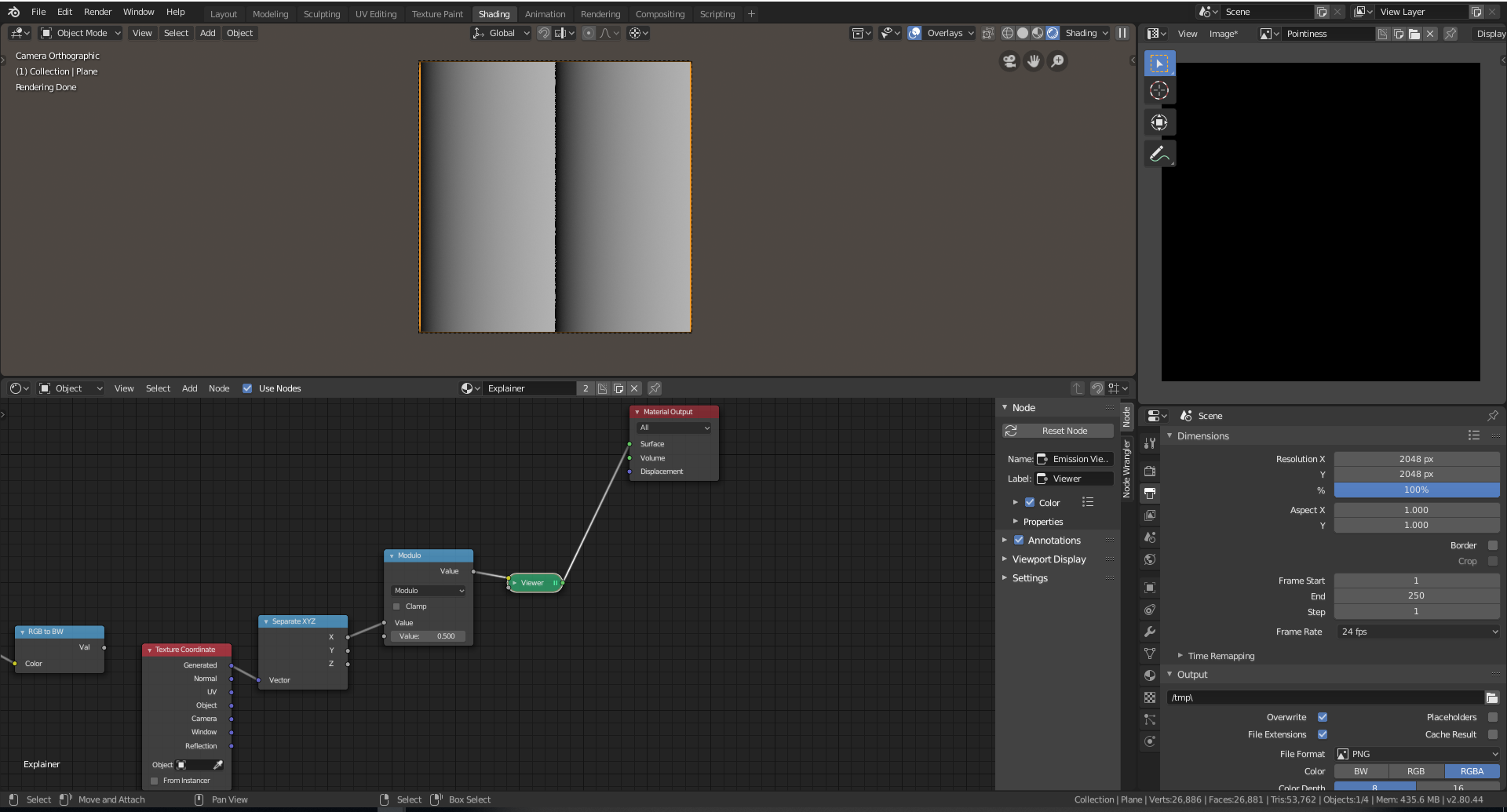
Modulo Example
The first thing we need to do is to separate our texture coordinates into x, y, and z components. Then we can apply a modulo operation with the lower input set to .5 to repeat our texture twice. Modulo will repeat your value by the inverse of the input so, 1/2 = 2 repetitions, 1/5 = 5 repetitions.
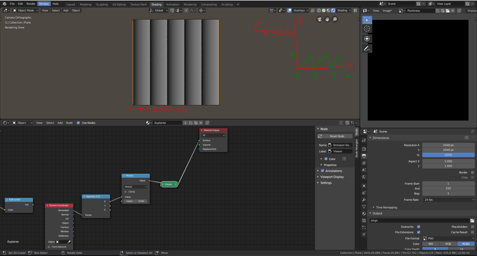
Modulo with 1/5
Setting the modulo node to .2 we get five repetitions however you will notice that our coordinates got significantly darker towards the end. This because modulo will give our repetitions a new range to whatever our input was, in this case, 0 to 1/5. To counteract this we can multiply our coordinates by the inverse: 5.
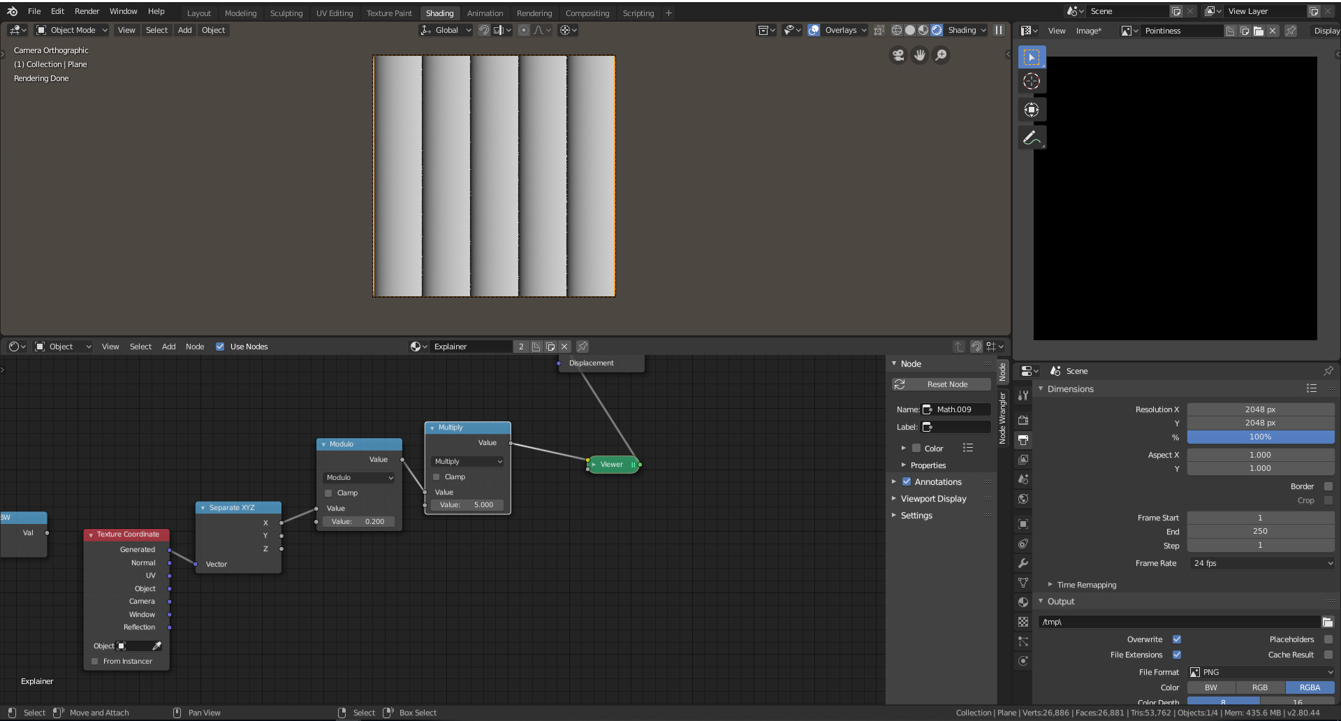
Modulo multiplied by 5
Now the x coordinate repeats from 0 to 1 based off of our inputs however the spherical gradient is mapped from -1 to 1 so we need to convert our 0 to 1 scale into a -1 to 1 scale. We can do this by subtracting .5 and then multiplying by 2.

Subtracting 5 converts our scale from 0 to 1 to -.5 to .5
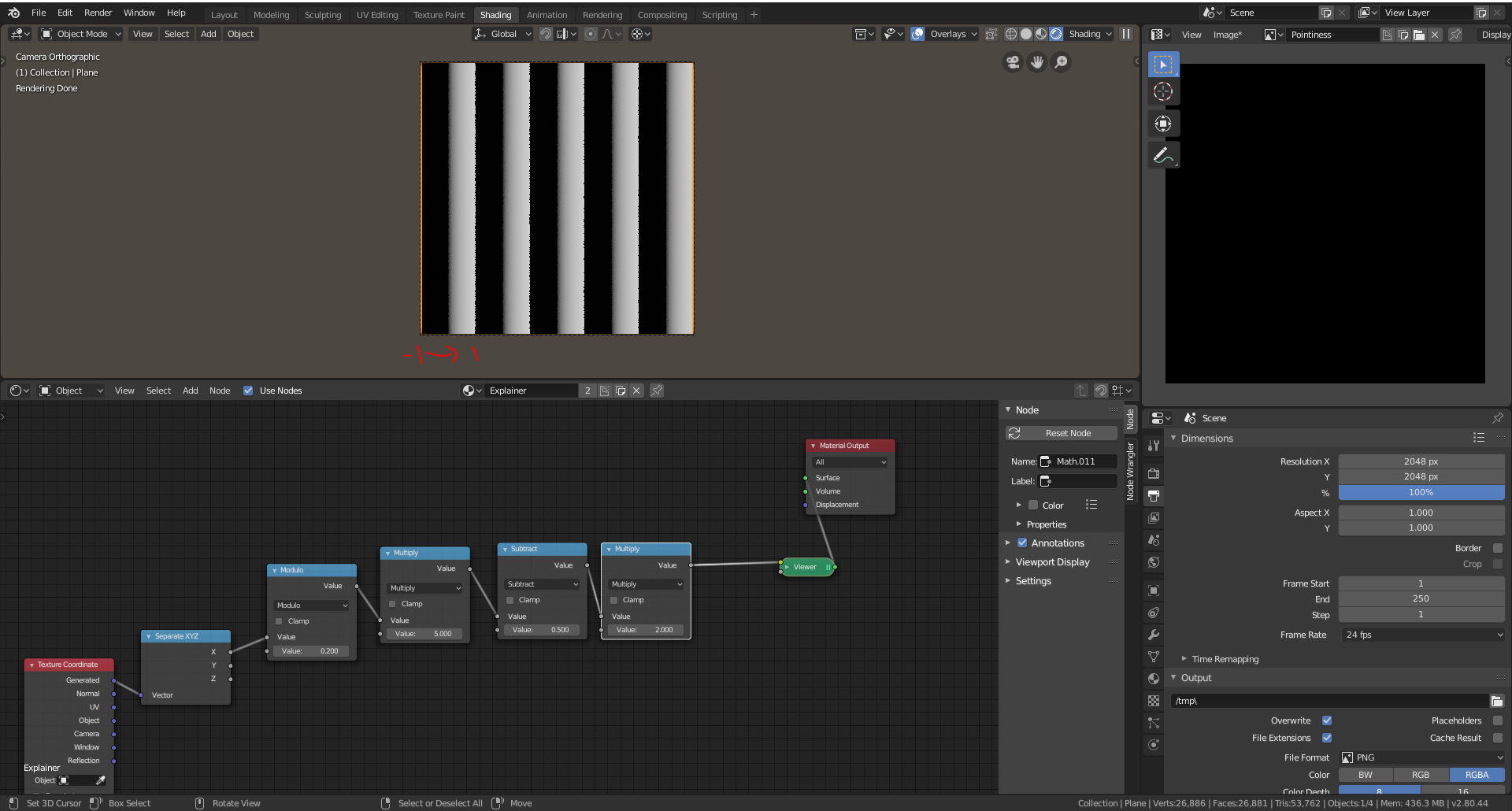
Multiplying by 2 converts our -.5 to .5 scale into a -1 to 1 scale.
If we switch from generated to object coordinates now you can notice that the left side of the plane is missing a -1 to 1 scale. This is because the object coordinates include negative values on a plane. To fix this, add an absolute value after the modulo operation.

-1 to 1 scale with negative values accounted for with object coordinates
Final -1 to 1 repeater
Now we can duplicate the math expression across the x, y, and z. Then plug a value input into the first multiply nodes. Create an inverse to plug into the modulo nodes by dividing the input under 1. Now that our repeater is done we should be able to create multiple circles and see our repeating coordinates.

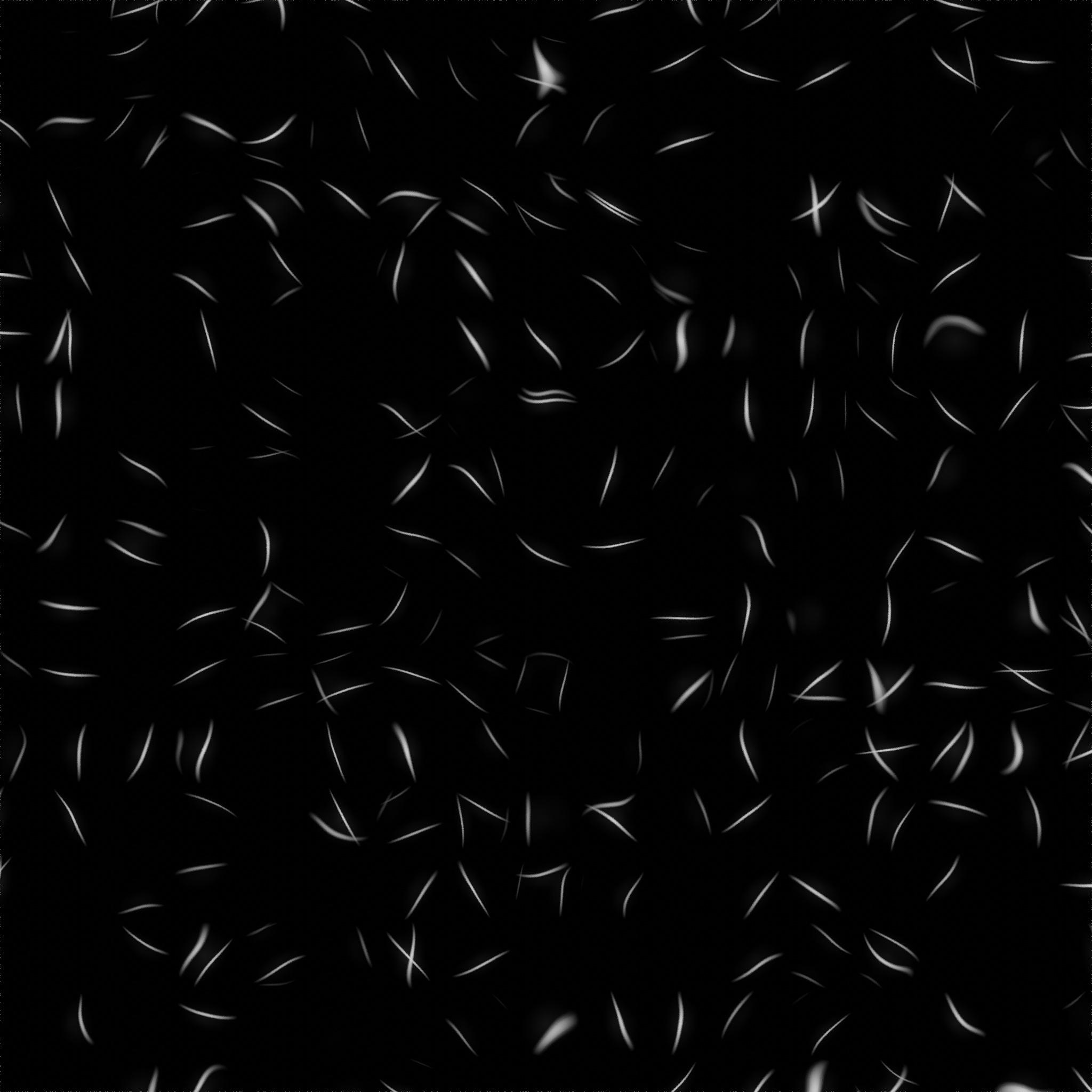
-1 to 1 Repeater with coordinates
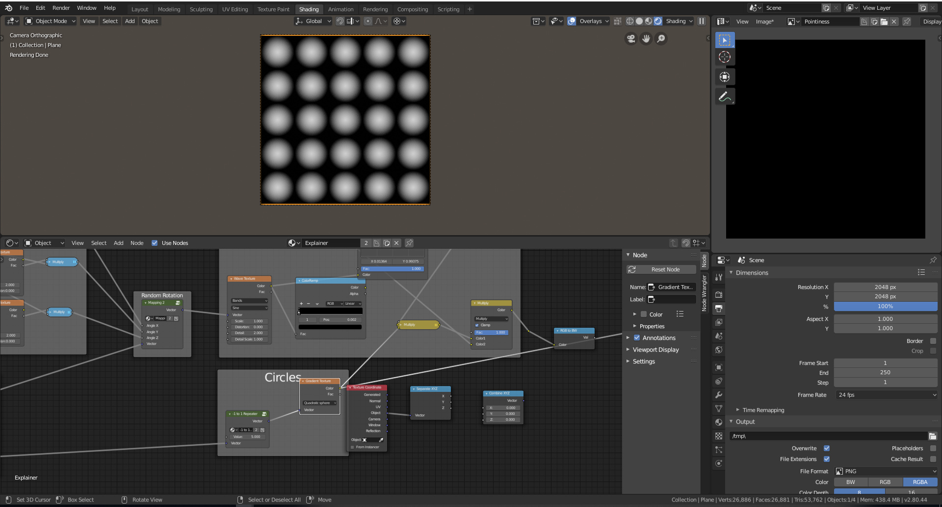
-1 to 1 Repeater applied to Circles
3. 0 to 1 Repeater and Pixelizer
Next, we need to create a 0 to 1 scale and a texture coordinate pixelizer. I will go fast through these as they use the same basic concepts as the -1 to 1 repeater.
0 to 1 Repeater
To create the 0 to 1 repeater first separate your x, y, and z components. Plug the inverse of the tile number input into modulo and the unaltered tile number input into the multiply node. The absolute value is not needed here because unlike the spherical gradient texture, the wave texture is mapped across all values, not just -1 to 1.

Output of 0 to 1 repeater.
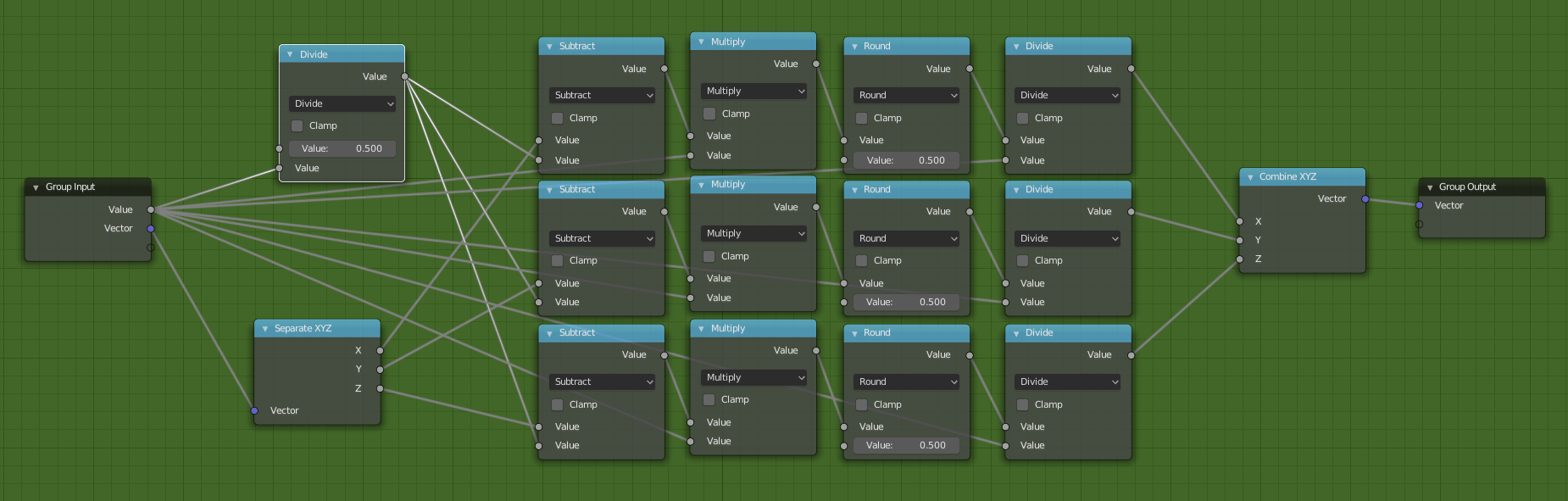
Pixelizer
To create the pixelizer, multiply the components by the input, round them, and then divide them back down by the input. That will create a result like this.

Pixelizer No subtraction
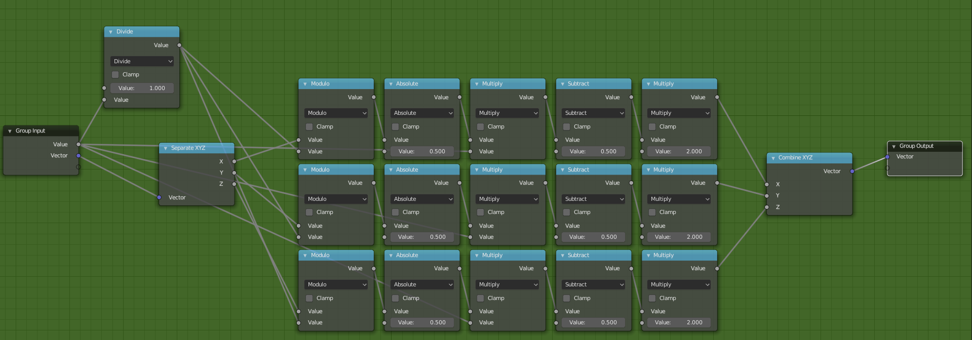
Because the rounding operation round based of .5 we need to subtract our coordinates by .5 but since we have 5 subdivisions we need to subtract by .5/5. To automate this use a division node and plug the group input into the math nodes.
The final group should look like this.
4. Wrapping it all up
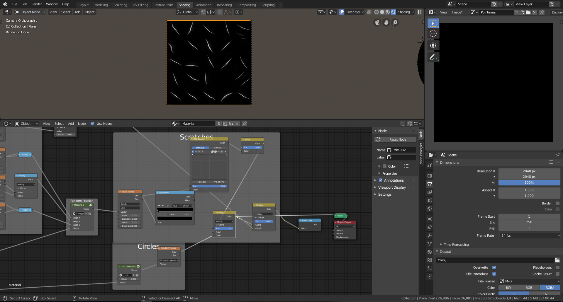
Now that we finally have our utility node groups we can finally create our scratches. This will be our final scratches node setup.

Final Nodes
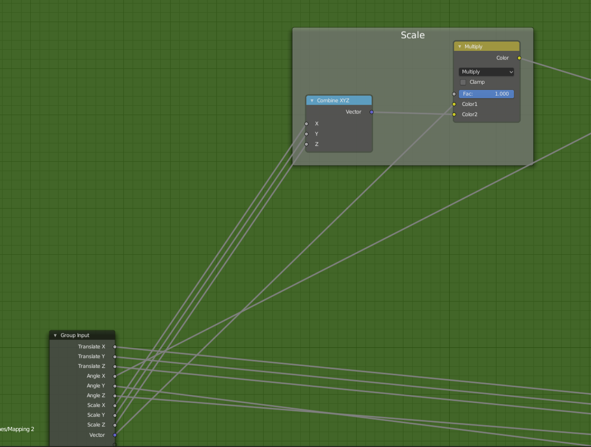
The group starts with the vector coordinates going into a mapping shift frame. This is equivalent to using the mapping node to translate the coordinates however it allows for access outside of the node group. I did this because due to the nature of the spherical gradient, it sometimes does not show if the onto a plane if the z coordinate is not aligned with the plane. Imagine it like this, a 3d sphere needs to intersect with the plane and where they intersect the texture is drawn. So if they do not intersect, nothing gets drawn.

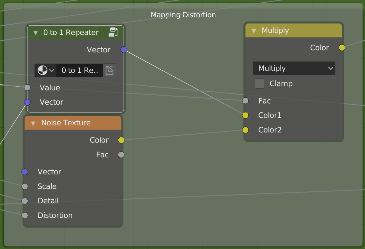
Mapping Shift Up Close
Then the mapping shift goes into the mapping distortion group into the 0 to 1 repeater. This is then multiplied with a noise texture. This will create the curvature of our scratches. The factor controls the influence. In my final node group, I exposed the factor into the outside node group.
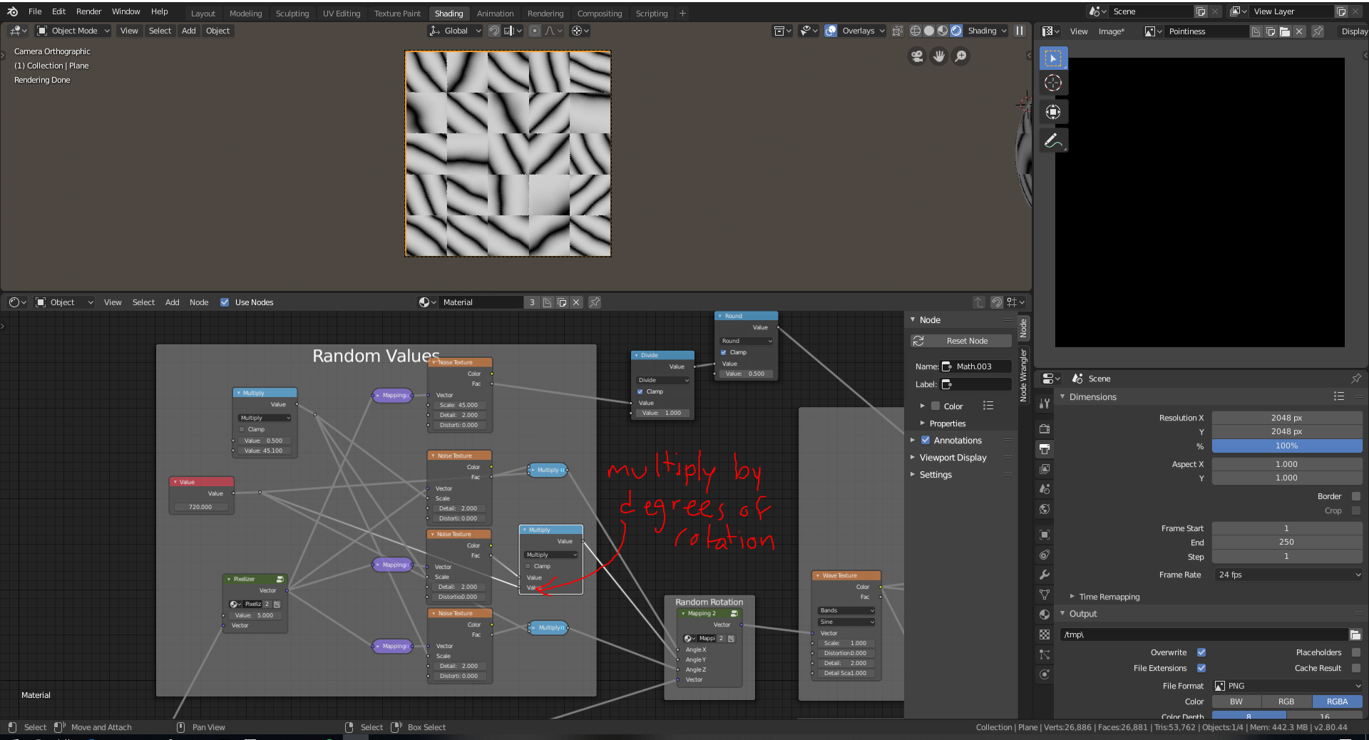
Next, we need to generate random values using a pixelizer.

Using the vector in a noise texture we can generate random cell noise which can be used to drive the rotation of our scratches.

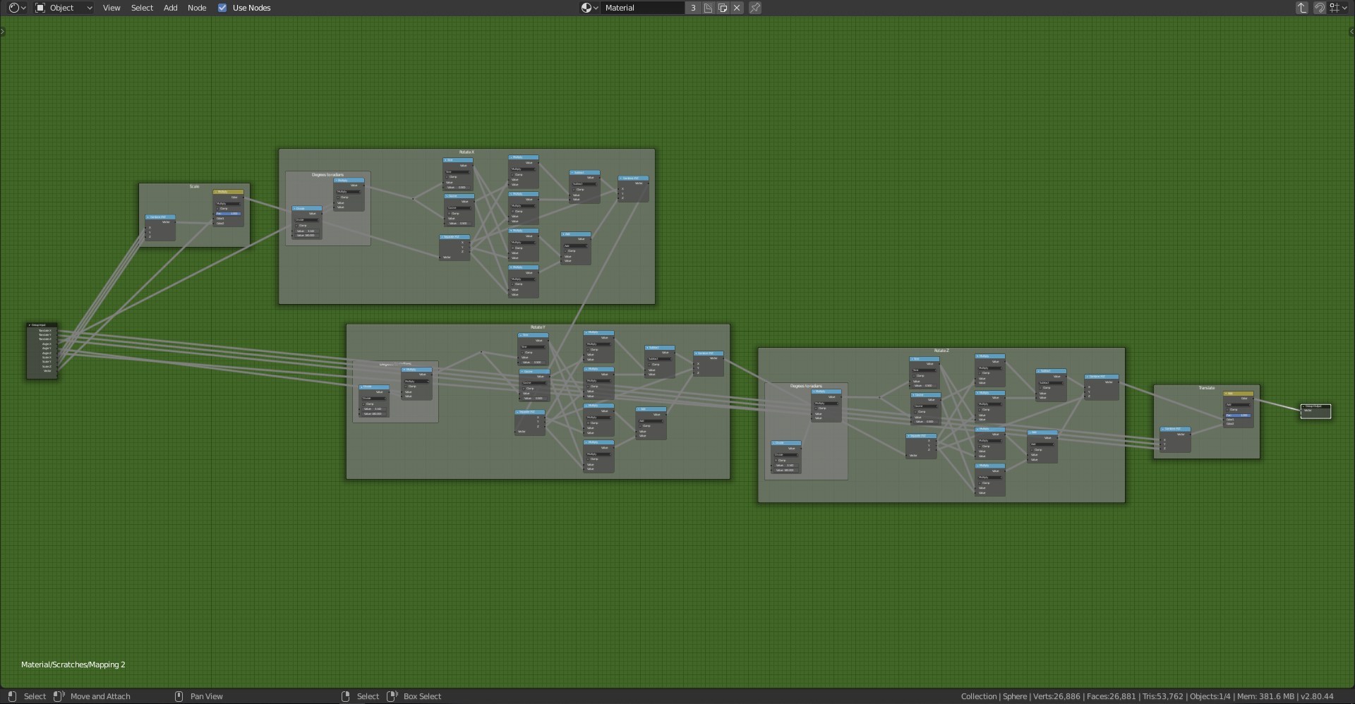
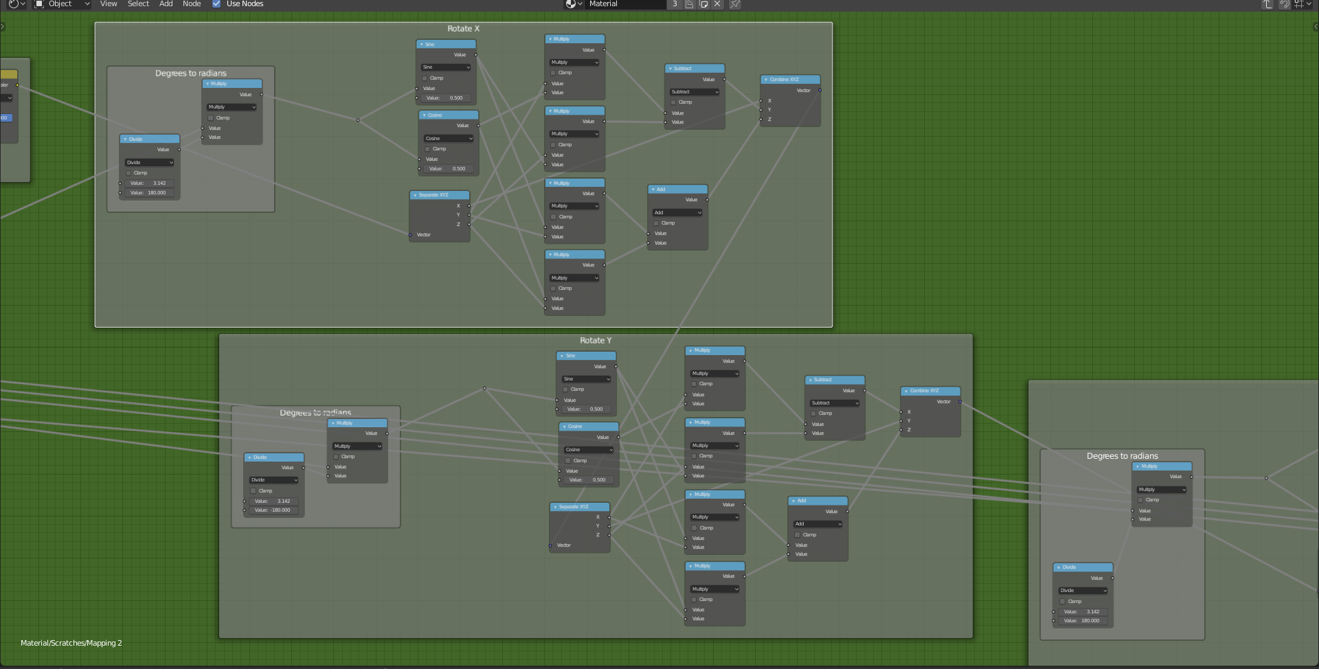
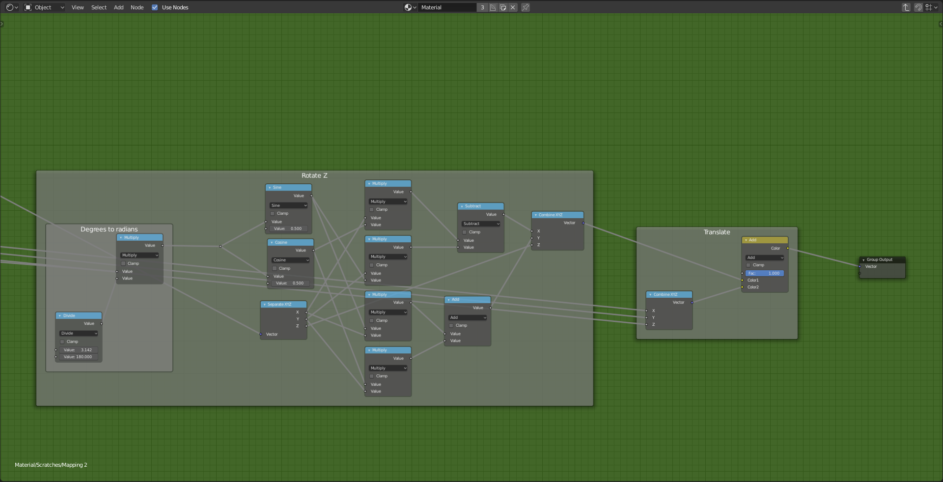
Multiply the noise by the number of degrees you want your cells to rotate and plug them into a custom mapping node with exposed inputs.
The mapping node is included in the .blend file so I will not cover how it works. (I’m not so sure how the rotation works anyway) He is a screenshot of the node if your interested though.
You can find more information about custom mapping nodes here:

https://blender.stackexchange.com/questions/58426/use-another-node-to-control-vector-mapping
https://blender.stackexchange.com/questions/93589/how-to-add-a-socket-for-mapping-node
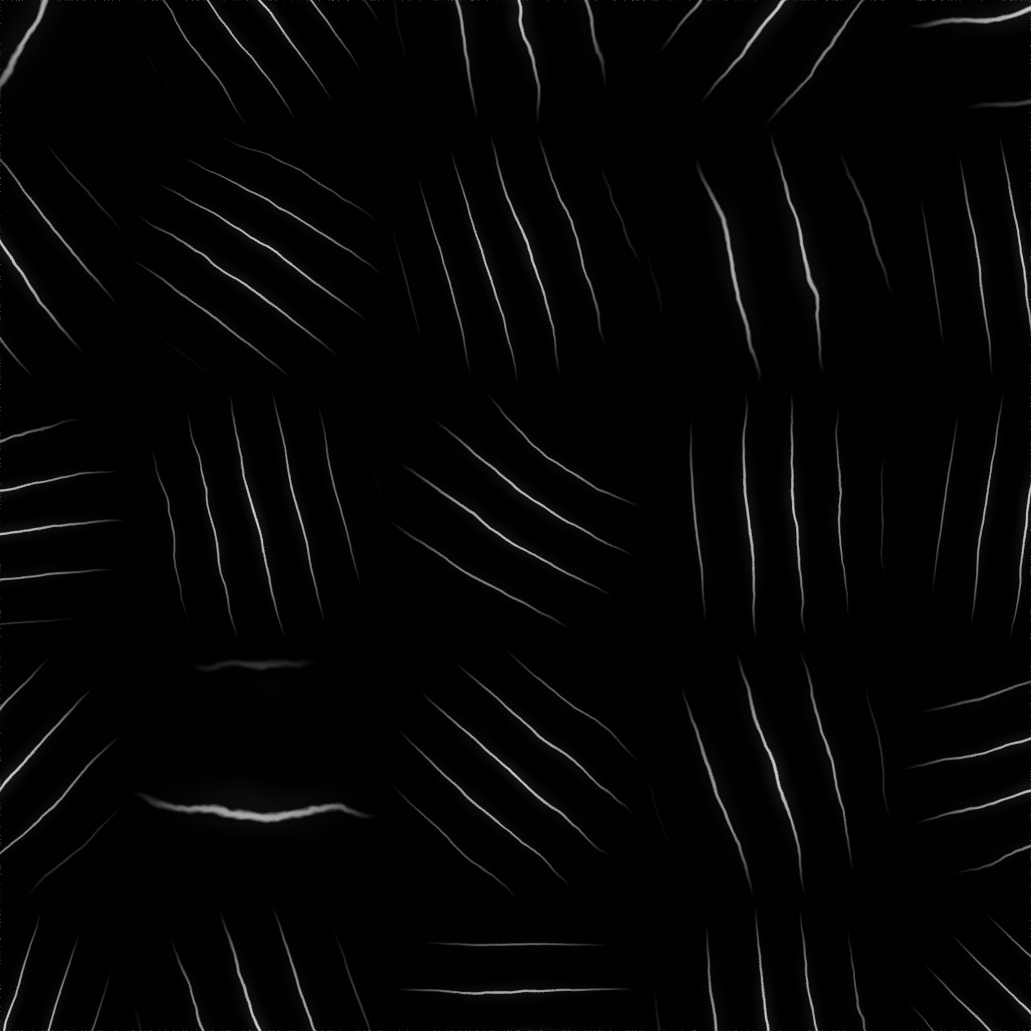
After we have randomly rotated our wave texture we need to multiply it by the spherical gradients.
Now that our scratches are starting to look like scratches we can mask some of them out using the random noise again.

The division node can be used to take away more or less of the mask. Divide closer to 0 will reveal more of the scratches and dividing using higher numbers will hide the scratches.
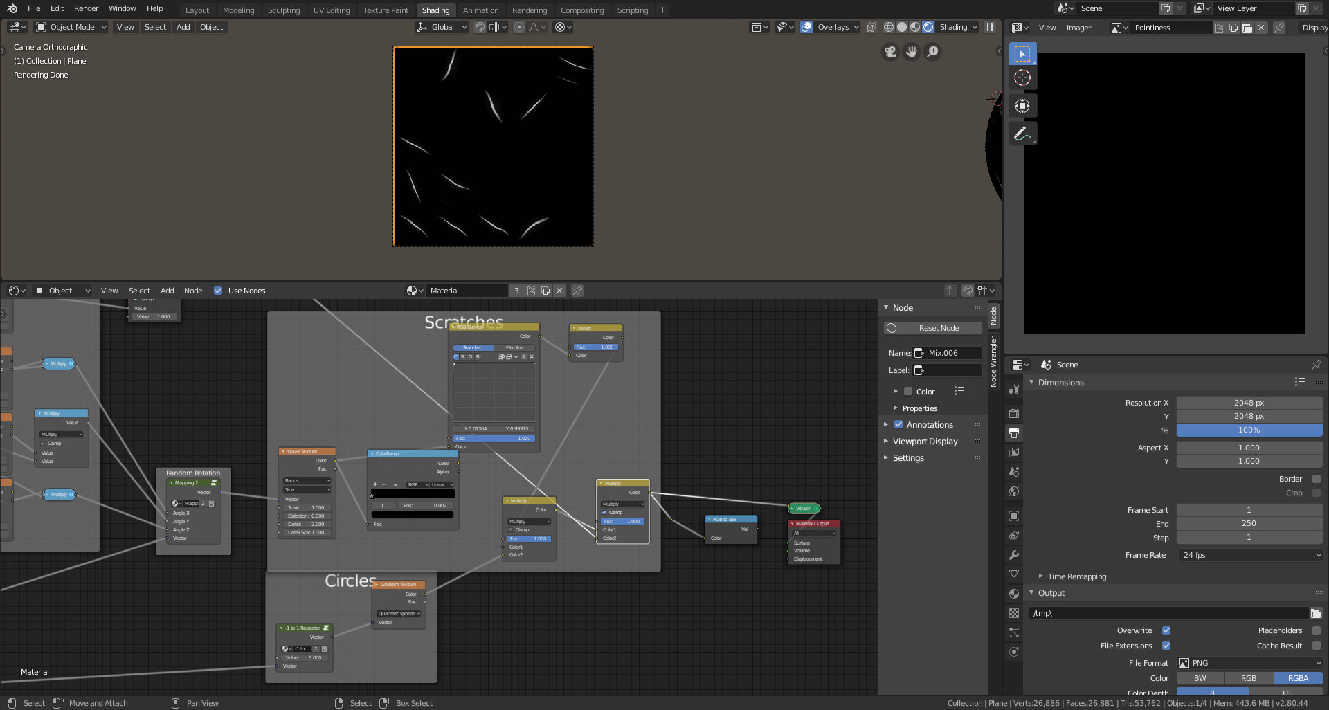
When you multiply the result with your mask some of your scratches should disappear getting rid of the uniform pattern.
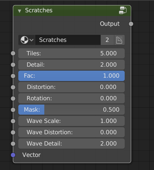
Now that you’ve finished you can put the result into node group. Mine ended up looking like this.
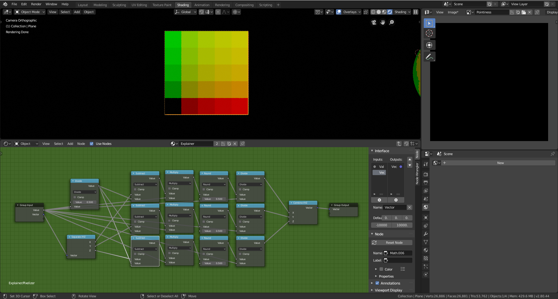
5. Wear and Tear
This technique is based on this Stackexchange Post
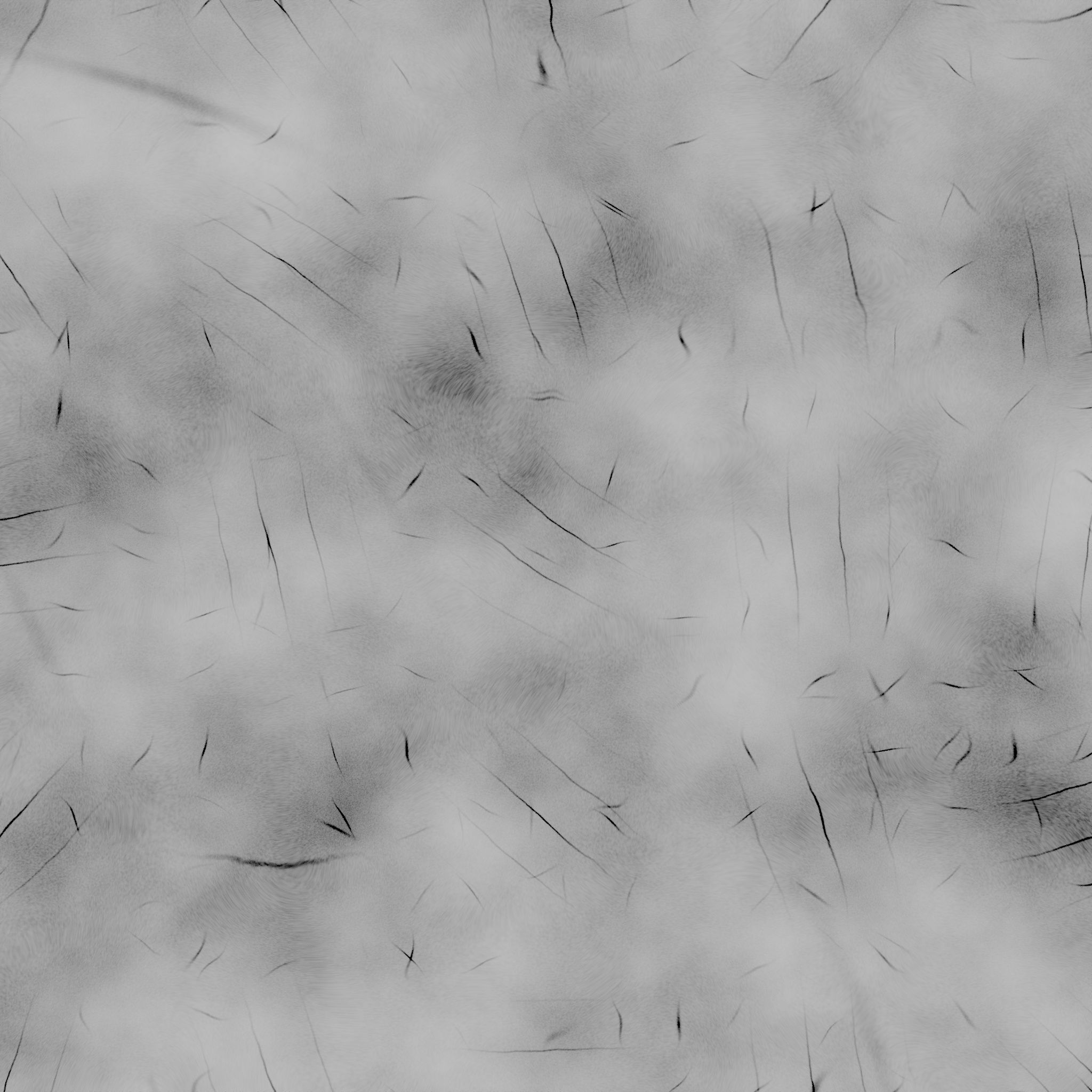
To create wear and tear start by burning two noise textures together to create our base.
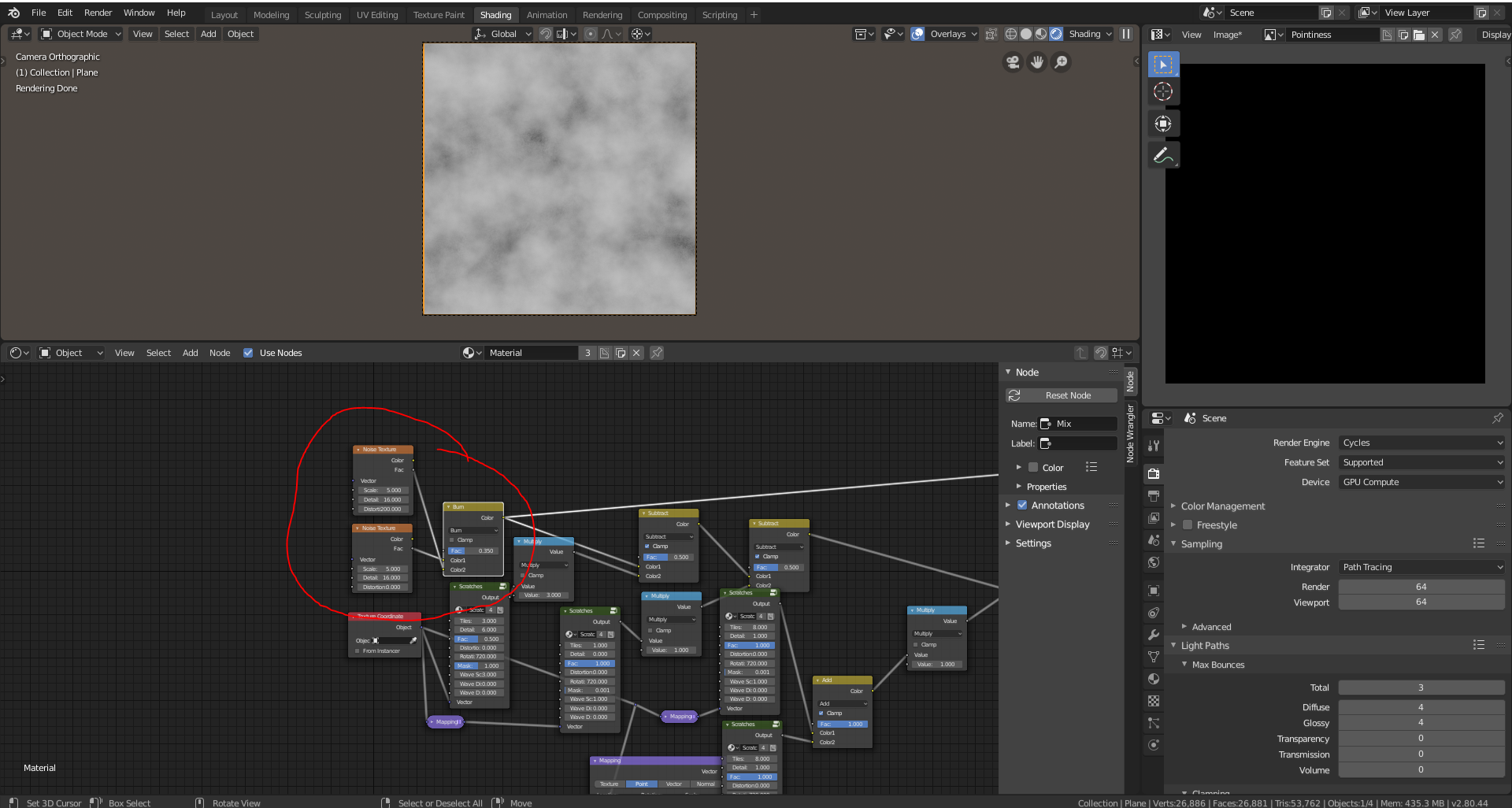
Then subtract the scratches from the base noise.
Create multiple layers of scratches to achieve the desired effect.
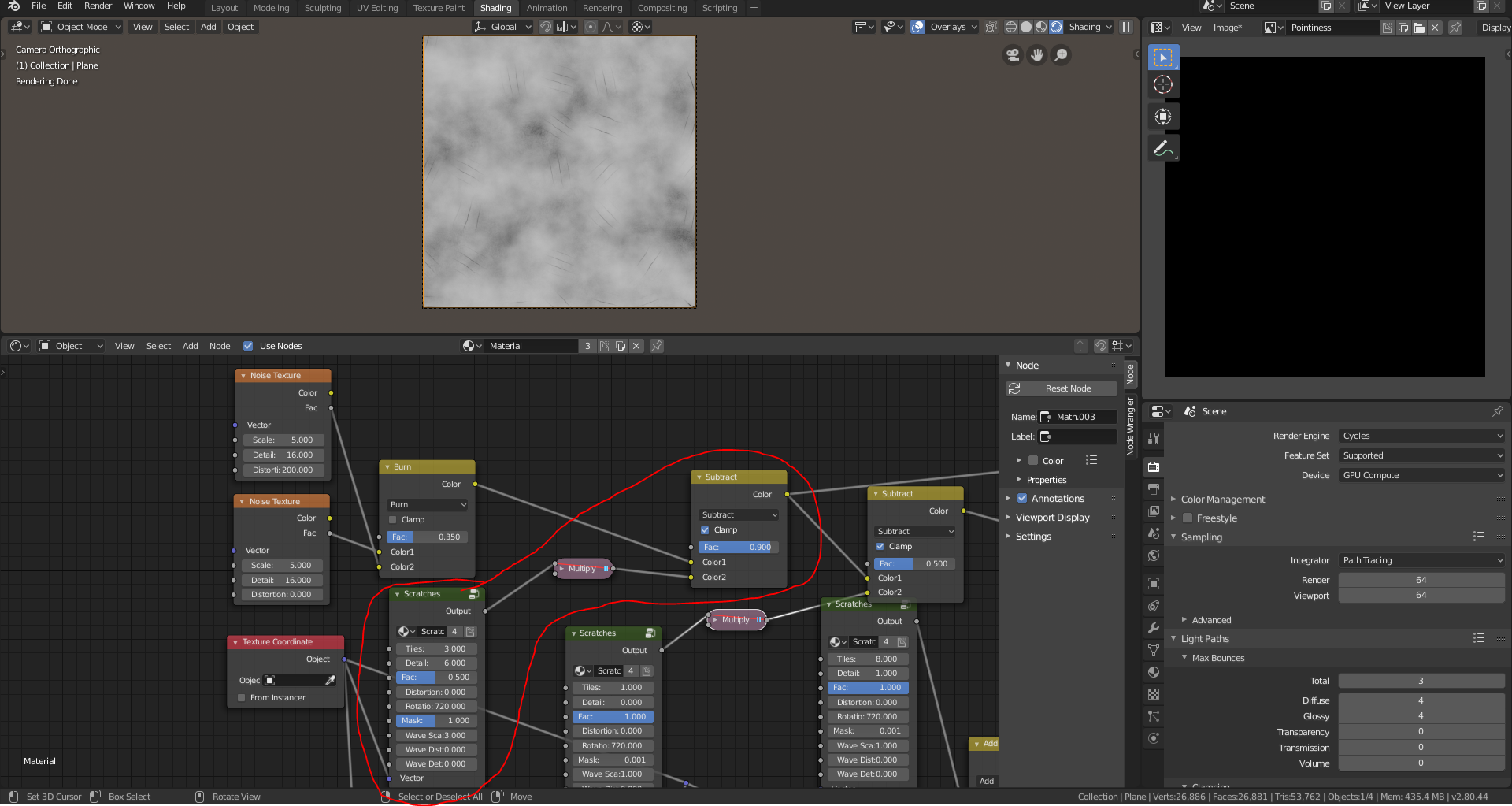
Create a geometry node add subtract 1 from the pointiness. Then add the created texture to the pointiness.
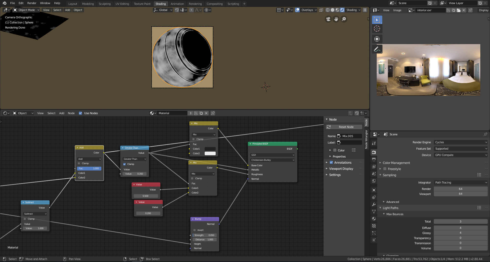
Clamp the values using a math node set to greater than to create the mask.
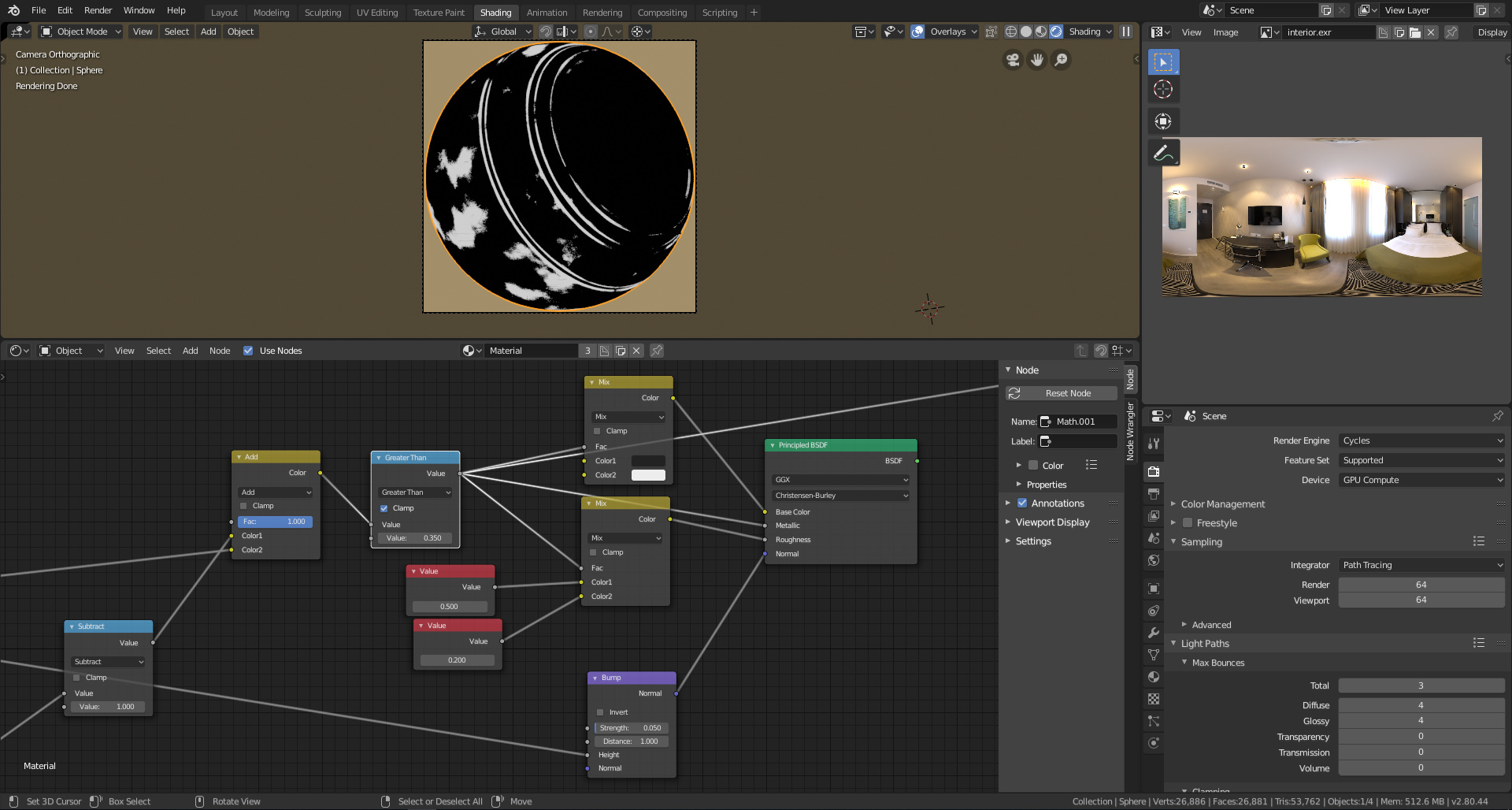
Use the mask to mix between two shaders.

TLDR
- Repeat spherical gradient
- Use cell noise to randomly rotate a wave texture
- Multiply the wave texture with the circles
- Use cell noise to create a mask
