My workflow was: Select the cylinder, Apply Scale, Make Seam, Unwrap. From this UV map I created my bump map, but this is not working properly. How can I make the stripes on the cylinder look even?
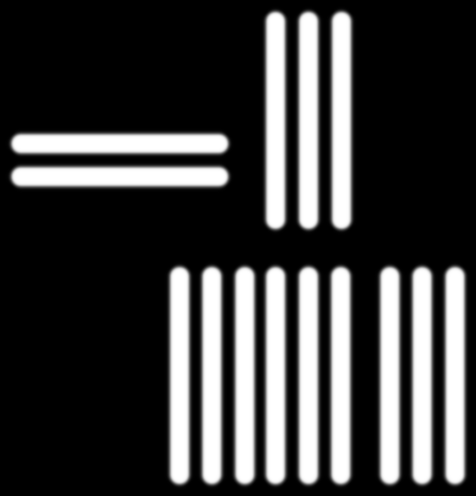
You original bump is 975x1015 and you exported UVmap is 1024x1024… okay by transforming bumpmap 19 pixels down this seems to be correct. But are you sure this two horizontal strips aren’t those causing the error in your rendering ???
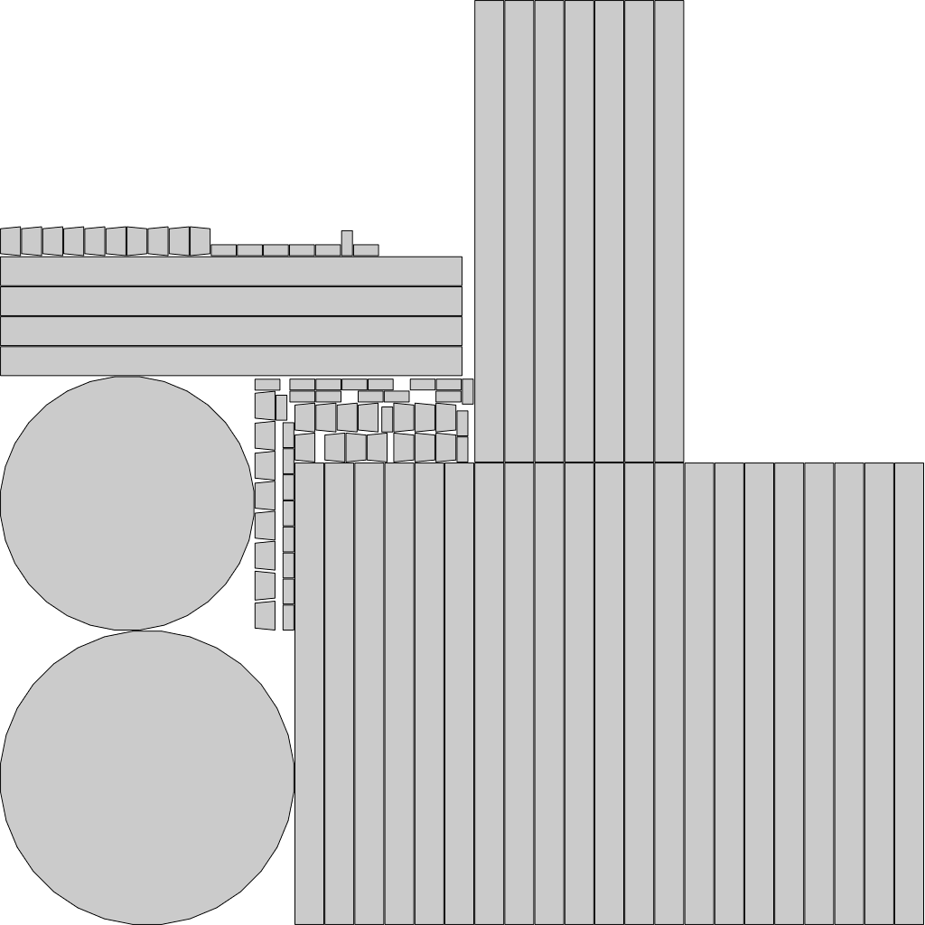
You are better off exporting the UV and building the Bump onto the sections you want equal. The map itself is not set with an equal distribution so even it would need to be arranged so that the bump unevenness can be hidden in the back…also Is this a Glass Material?
You may need to cull the back faces…and subdivide the section to get better results…with a bump like this as well as a Glass material Lighting will play havok with the reflections … Grabbed your Bump from above…
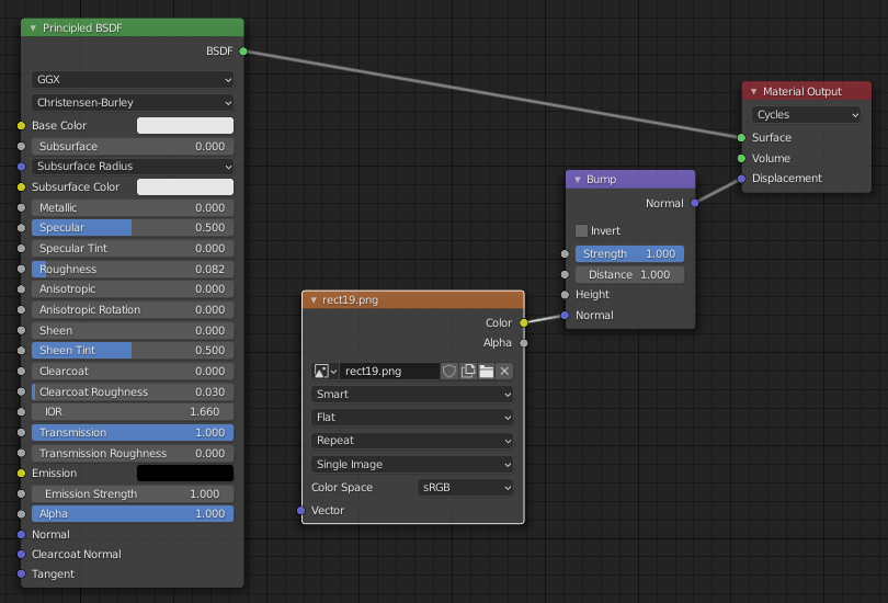
So pretty standard setup… I was wondering about the mapping of the UV coordinates. Have you made sure that the image you load as a bump-map is correctly aligned to your UV?
Nothing to do with the problem, but the bump distance is 1.0 - I feel this is way excessive for what I think this product is. 0.003 would mean 3mm difference from black valley to white ridge.
The node setup looks wrong. The image goes into bump node height instead of normal, and the bump normal output goes into Principled normal instead of displacement. If using the displacement material output, you should use an appropriate displacement node instead - I can’t imagine the bump normal output would produce anything useful for displacement. Whatever goes into displacement scale using microdisplacement is what should be used as bump distance. For a professional product shot I would consider microdisplacement over fake bump maps.
In addition, you may want to use cubic interpolation, use 16bit images (but here I think 8bit will work just fine), use large images (probably fine here), and use non-color data.