I’m trying to create a material that works like a caustic map generator. The core points of the idea is pretty much Secrop’s technique explained here in this thread: Caustics in Cycles . Imagine a fairly simple scene: a plane, a glass sphere and a point lamp. I want to calculate the caustics caused by the point lamp and the glass sphere on the plane. What’s the basic idea: in Path Tracing like Cycles, rays are emitted from the camera to hit the scene so the engine is able to render the image. In a VERY awkward way of putting it, it’s like the final render are all the points in the scene being “illuminated” by the camera. So, if we put a camera at the position of the light, we can approximate that every point being rendered in the picture (key thing here is including those points reached by the camera with the help of the refraction) is a point reached by the light, and so, we can picture what portions of the sphere shadow is illuminated by the caustics. Than we could bake this texture of the plane and simply add it before the final render.
Is it possible to create an OSL material for the plane that highlight only the portions of the plane being seen by the camera? Imagine like if any ray emitted by the camera, once intersects with the plane, “paint” this point of intersection. I believe that at some point, the engine kind of knows the points of the plane the camera was able to reach or not, so is there a way to extract this information?
Again, as I previously stated, OSL alone won’t help you. The only difference of using my method with OSL is that you can have multiple samples in the same rendering, and you have access to ray area and its derivatives, so you can use it for filtering and cleaning the final texture…
Imagine this: the camera has a field of view, and in this area, a fixed amount of light is throwned. Each pixel will represent a package of photons with a fraction of the light from that area. With my method as is, the coordinate from hitting the plane is stored in the rendered image, and therefore (because samples are averaged) I can only have 1 sample per pixel, with no filtering. In OSL I can store every hit in a file, and the rendered image is not so important… That way, I can have multiple samples per pixel, as the final pixel won’t be used.
Now the part that you’re missing: you end up with a list of coordinates; either in a 2d array (the rendered image), or a 1d array ( the osl shader output). So you need to convert the list of coordinates into a texture where each coordinate has the sum of all samples that correspond to that same coordinate. Unfortunately, there isn’t any operator in blender for doing that, and you need to do it by yourself. This is what requires the histogram! An histogram transforms a list of values into a list of occurrences. For example, your end list is something like this: [b, e, c, d, b, c, d, b, b] (each value means a specific coordinate), but you need something more like [a=0, b=4, c=2, d=2, e=1, f=0]…
In the next picture, you can see the rendered image from the camera on the left side, with only the UVs of transmission rays… On the right side is the output of its histogram:
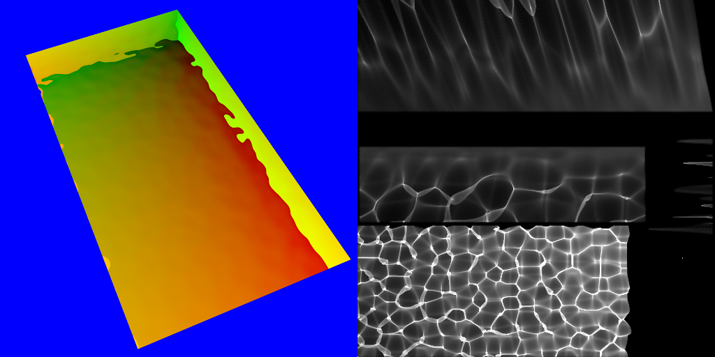
This is what an histogram is, and that’s exactly what the script in that old thread of mine does.
So in the end, there are no miracles… just hard work and calculations.
Doesn’t cycles have pretty poor caustics anyway? Not saying that it’s a bad idea, it’s in fact really cool, I just think that it might work better in an engine like luxcorerender
But think about baking textures in Cycles: with this, you can generate a texture which gives the results of light hitting the object, with the appropriate locations, kind of like what happens around 10:15 in the following video: https://www.youtube.com/watch?v=sB09T--_ZvU . The texture generated knows which parts of the plane were hit by the light rays transmitted trough the glass Suzanne, given the position and properties of the objects in the scene. Imagine this exact same situation, but instead of light rays emitted by a lamp, it would be camera rays emitted by the camera; instead of asking Cycles to get the points in the plane where the rays coming from the light (and refracted by the head) hit, we would ask it to get the rays coming from the camera (and refracted by the head).
One other thing: where exactly is this histogram located? Should it be that new texture you asked to add in step 9? Here is what I’ve done, so we can be sure if I made some mistake:
1-I’m using that scene with the plane and Suzanne glass head. Don’t know if this changes something;
2-For the plane, which will receive the caustic shadow, I used that node tree in step 3;
3-Created a new UV map in the object data section (now the plane has 2 UV maps, “UVMap” and “CausticUV”). I set the “CausticUV” map (the one I created) as active for rendering, and set this very map in the UVMap node in the plane material
4-The camera is in the exact same spot as the single point lamp in the scene, and pointed towards Suzanne (the object which will generate the caustics). All of Suzanne is within the field of view of the camera
5-Created a material for Suzanne, called “Refraction”; it is a single refraction node plugged to the material output, color total white
6-Set the world background to pure blue. Now, if I render the image, I can only see the plane through Suzanne, like the right side of your picture
7-The scene to be rendered consists of the plane, Suzanne and the point light source with a strenght of 0
8-Set the render output to be PNG, RGBA and 16bit of color depth. Just one sample of rendering, no transparent shadow, no caustics, Diffuse and Volume bounces set as 0.
9-Changed the exposure from Blackman-Harris to Box
10-Rendered the scene. Name of the rendered image is simply “Render”, and I create a new texture called “Caustics”
11- Ran the script. No error accused by the console
12-The picture in the “Caustics” texture remains black.
The problem about baking caustics is that Cycles is not optimized for it. And any change in this regard must be done in the source code. The good news is that cycles and blender are open source! 
About the script…
Step 3 - For a setup so simple, this step isn’t needed. It’s more usefull when the receiving object is large and the caustic area is small.
Step 7 -No need for the alpha channel, can be RGB. I prefer Openexr_float(full), but I think PNG is ok.
Step 9 -Filter to box and color management to None or Linear.
Step 10 - “Caustics” texture should be 32Bit float.
Step 10.1 - Save the file, and open it in another slot!!! 
Blender has a known limitation about accessing the Render Result from Python… must be a stored image.
Step 10.2 - edit the script, last line where says ‘Histogram(D.images[your_render], D.images[your_new_texture])’, and change your_render and your_new_texture to the corresponding names of those datablocks, like D.images[“render.png”]
the script divides all values by 400… this can be too much or too little depending on the amount of samples, so save the caustic texture (preferably in 16Bits or more) and edit it if needed.
It was the step number 10.1, I was trying to acess directly from the Render Result, lol. Now it’s working great! If we increase the number of samples in the first render (the left side in your image), does the caustics get more smooth?
Samples should stay at 1 per pixel. But if you render the image with a bigger resolution, you’ll get better results. I normally use something above 2048^2.
So, from what I got so far, the output of the UV map in the object is a mix of 2 colors, red and green. The amount of red would represent how far in the x direction you are, the ammount of green shows how far in the y direction you are. There can’t be 2 points in the material with the same color.
With the background set as pure blue, the only pixels with such colors in the first render would be those from the plane (refracted by the glass, given the light path node). And because you can’t have 2 points with the same color in a given UVmap, by calculating what amount of red and green each pixel in the first render shows, you can safely predict what point in the plane you’re looking at. Is this how the code works?
It’s an UV coordinate. If your UVmap has overlapping faces, then the same coordinate is shared with all those faces.
Also not a rule… the blue color or black is still an UV coordinate, the (0.0, 0.0). So one must be a little carefull to place the faces at another location… (or choose another background color pointing to a coordinate with no faces).
If you look closely to the histogram image I posted above, you’ll see that the bottom left pixel is white. In fact that pixel is extremelly white, way above 1000 in all channels. That’s because of all the blue color on the initial render.
Apart from these details, that’s basically how the code works.
There’s still much more that can be done here… but a more complicated math must be used. For example, dealing with total internal reflection, or fresnel quantities for reflection/refraction separation, or even using derivatives to produce better caustic maps with smaller renders.


I’m just uploading the results of some test I ran. As I said, I don’t know how “correct” these caustics are, but I really liked the results. I think anyone trying to create caustics in Cycles should give Secrop’s method a try, I’m literally in love with this, lol ![]()
Anyway, my little caustic problem is solved. Those are pretty good results, considering that this method employs nothing but Cycles itself to achieve it.
The teapot glass is made to simulate difraction of wavelenghts (I had to create 3 different caustic maps for each wavelenght and add in the final caustic map) and in the second picture, we have a glass with roughness of 0.2, hence the “blurred” caustics
They are just partly correct. Light going through transmissive objects follows different paths, and this method is measuring just one. So the result is just incomplete, and there should be much more light hitting indirectly the plane.
I was wondering, thue UVmap only needs to colors (Red and Green) to represent it’s coordinates right? Is there a way to add the color blue in a way where we can approximate the volume absorption of the material?
For example, picture a glass sphere, with yellow glass and a absorption color of pure red. Part of it’s caustic should be colored yellow, because of the light rays which spent “less time” inside the sphere, while thos rays which spent more times (they bounced more) suffered more of the volume absorption influence, so they should leave the sphere with the red color. What we need is a way to creat some sort of “mask” in the caustic maps which will represent those caustics formed by less absorbed rays from the more absorbed ones. And this is where the addition of the color Blue comes in
In your setup to create the caustic map, instead of a pure white glass material, the object to generate caustics could be a pure white glass material with a blue tint in absorption (the absorption could be done with that LightPath Node trick). However, the blue color coming from the absorption should be added to the red/green color of the UV plane behind (the values of the red and green colors from the plane should not be altered). Do you think this is possible?
Yes, it’s possible. You need to make the color pure blue, so it doesn’t change the Red and Green data. Perhaps it might be better to use a volumetric emission, instead of absorption.
The script will need some changes also.
Eu suponho que Eusébio seja nome português, Por isso mirei escrever o meu comentário em português.
Eu gostei bastante dos resultados, poderia enviar o .blend ou então mostrar os nós? Gostaria muito de puder testar!
I suppose Eusébio is a portuguese name, so I will write my comment in Portuguese.
I really liked the results, could you send the .blend or show the nodes? I would love to test!