I have a normal map and a height map. Can I combine the data from the two to generate a vector displacement map?
What do you mean by “vector displacement map”, what are you going to use it for?
(I know what it is, I want to hear your definition of it.)
Those maps are already kind of displacement maps: the normal map has directions and magnitude (edit: correction, no magnitude! normals are always unit length = 1), the height map has just the magnitude (with all directions being “up”).
I played around with it and got some interesting results. It didn’t add much more detail than just the height map, but the idea was to use the normal map for displacement along the surface’s x and y coordinates (in tangent space) and the height for z displacement.

Ohh right, I corrected my post above. A normal map has only directions, all magnitudes / lengths are always 1.
How about this: the normal map gives what direction the displacement happens, and the “height” map is just a multiplier that says how much displacement is going on in that direction.
So it’d be more like an “intensity” map than height map.
All vectors encoded in the normal map have a length of 1 and arbitrary directions. The scalars encoded in the intensity map scale those vectors from the normal map, such that black means no displacement at all, and white means full displacement (according to some constant value that you tweak to something you like).
This constant is an Input -> Value node.
There’s still not enough information there for a true vector displacement, though. Normal maps are in tangent space, so they don’t carry any information past 90* to the surface.
The only way I can think of for this to be possible (but impractical) would be to generate a displacement map between the base mesh and secondary details, then generate a normal map between the secondary displaced and tertiary details. In effect, you’d have information up to 180* of the base surface.
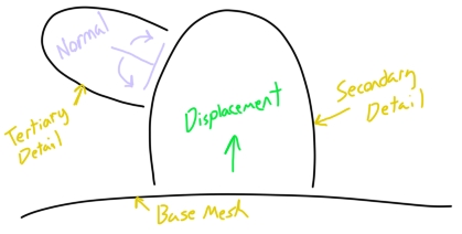
I say impractical because at that point, you might as well just generate a true vector displacement from the get go. Can you do that in Blender yet? I usually create these in Zbrush, so I haven’t looked.
Yeah, there’s probably no easy way to generate a true vector displacement map from these inputs. Now that I’ve figured out that something can be created from these two, I guess I be asking whether this is worth going. I like the prospect of being able to displacement in more than one direction, but do I gain any extra details with this? How much detail/accuracy is lost when using a height map instead of a vector map? Would vector displacement help me reclaim these details?
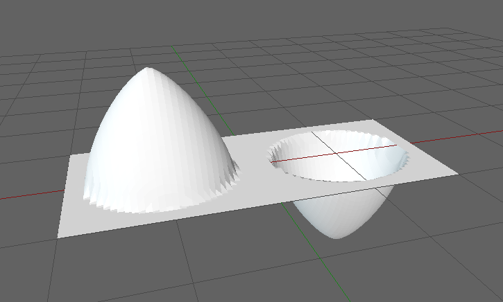
In your height / magnitude map, if you consider 0.5 as a baseline of no displacement at all, then anything less than 0.5 will let you go in negative directions so you can do 360º displacement from the surface point, even with a tangent-space normal map.
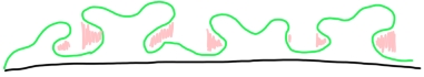
A vector displacement map can describe concavities on a flat surface, so the parts shaded in red are what a vector displacement map can produce.
I’m still not following how a normal map carries the necessary information, but I’d be interested to learn. Can you provide an example?
It’s nothing of consequence, it doesn’t solve the OP’s problem.
Like you said, a normal map can only represent directions in a hemisphere, not beyond it.
If you want to represent directions beyond it, you can use a “mid line” value in your height map like the Displace modifier does, a value that defines what is “zero displacement”.
Any values above it mean a positive displacement and any values below it mean a negative displacement.
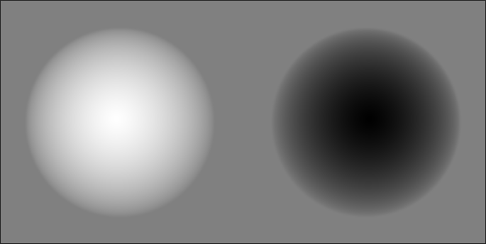
So a single normal map, coupled with a height map that has a midline value, could represent directions on both a positive and a negative hemisphere (a whole sphere).
Ahh, I see what you’re saying. In your last post, I though you meant that you could use a normal map in the same way as a vector displacement map.
Hi, there’s perhaps a way to do so, but if you’ve baked from a high poly to low poly mesh and still have them around you might as well use them to bake a vdm directly in that known workflow. Speaking of try this
and check his other videos.
The node group is in the linked blend https://drive.google.com/file/d/0B1mc80hFkBqcZHAxNUwtNENOTkU/view ~45MB
4 Likes
just another way may be
use the new AO nodes in latest build
can add equivalent or better Dirt Map = AO Map
to any models
and very flexible and poweful
check out this video
happy cl
1 Like