I have a problem with mechanical object rigging - specifcally with closed loop linkages. The problem is actually identical to this one asked here, which is still unsolved:
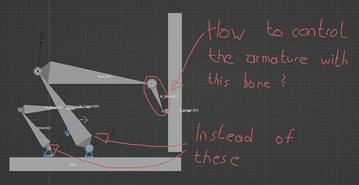
The idea is to control a rig from the end bone, rather than from one of the start bones. This can be done relatively easily with a 4-bar linkage like so:
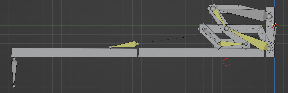
Although similar in principle, more complex hinges such as the 7-axis hinge above aren’t so straightforward. Every chain variation that I have tried seems to result in a dependency cycle.
I’m wondering if this could be a practical case for the iTaSC solver since it can handle more constraints? Also since the solver was recently updated, it seems more accessible to these sort of projects.
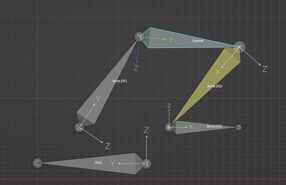
Select the red circle, and translate it to operate the hinge.
It’s basically three sets of IK contraints, a couple of extra bones for the IKs to target, and the control bone, which is positioned in that central location.
Hey magpie, thank you very much for looking into it. The bus door example is just the sort of thing I’m looking into, where ideally the hinge can be controlled from an interaction point - such as the door handle.
I guess to do this, the end bone would need some sort of IK or tracking constraint that uses the handle as a target. So the rig would need to be controlled by the orientation of the hinge’s end bone.
Anything that’s able to move the control bone would do the job.
That could be directly with parenting, or via a driver. As it’s only the horizontal motion that actually moves things, you could parent the control bone (keeping it’s offset) to one next to the handle. Although that might introduce a dependency cycle, if the parent next to the handle is a child of the overall system.
Yeah, changing the parenting will definately introduce a cycle.
It often helps to think backwards when animating and rigging.
Rather than getting a hand to control the door handle (or sword, or cup), it can often be better to constrain the hand to the item instead.
Using the hinge control to drive the door, which then drives the hand that’s constrained to it, can lead to a simpler solution.
In this instance, parenting the door-handle bone to b.004 (I apologise for the naming scheme ), will get it to keep the correct position throughout the movement.
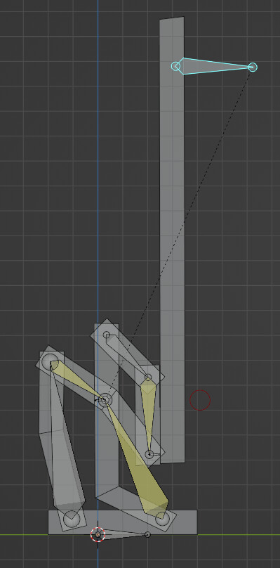
I definitely agree that constraining the handle to the door is the most straightforward way to get the result, then perhaps adding a driver can act as an interaction point - even if the positioning would likely be a bit off. Where the control point of the hinge really becomes an issue is when the series of hinges is increased. So let me complicate this a little more.
If we add a second door, with a single pivot point connecting the two and add an IK constraint pointing at a handle, the rig becomes more difficult to control. The angle of the second door would become dependent on the location of the handle.
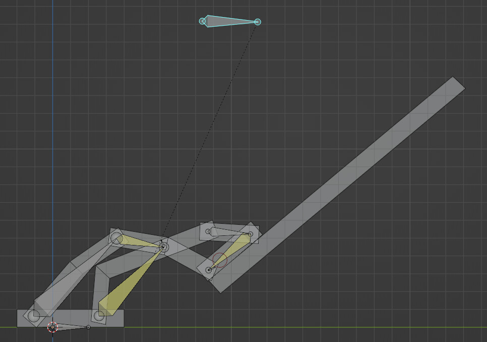
Of course this is the inverse kinematics issue, where we want to control a rig from an end effector and everything will behave accordingly, rather than setting the position of each link from the beginning (forward kinematics).
This is where the control point of the hinge particularly starts to matter. The best solution for this would be to use the handle as the IK target, with the hinge connecting the doors as the IK bone and the chain length including the end bone of the first hinge. This would then affect the orientation of bone.004, and then the positioning of the rest of the hinge.
One option for difficult situations like this, where you don’t want to just solve the math and use drivers (I certainly wouldn’t want to) is to graph out the relationship of one bone to another and then flip that graph, to get the input that will get you a desired output.
So in practical terms, first we need to graph it. We’ll keyframe our existing control to the minimum of its range at frame 1, the maximum of its range at frame 360 (for example), set the graph to linear.
Then we’ll make an empty that gets its X driven from our existing control and its Y driven by the desired control. (Importantly, in whatever space we want to measure the desired control, like probably not with the same parent.) Over 360 frames, this empty will describe the relationship between these two bones.
We can turn this into a curve or mesh with btracer addon (bundled with Blender) or now by using simulation nodes. Then, we can give a bone a particular X or Y position along the graph and give it a shrinkwrap on project onto the graph object to acquire the other coordinate. If we read the X from a given Y, we’ll get the output on our existing control needed to match the input we want from our desired control.
Let me throw in a different solution that would solve the problem i had in my thread: Hinge_zebra.blend (1.5 MB)
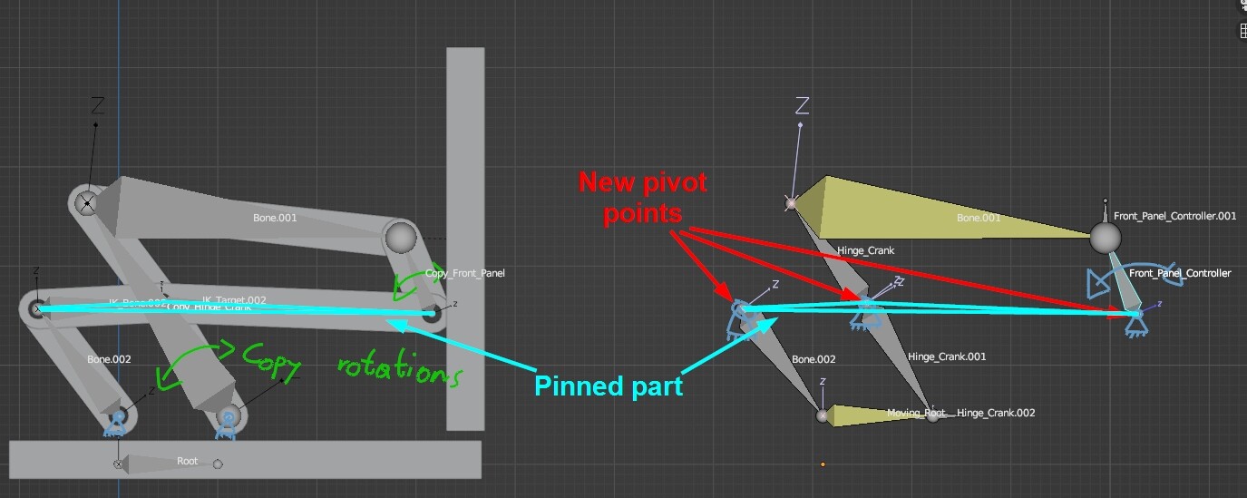
The idea was to create an additional armature that would control the inital armature with a couple Copy Rotation constraints. Instead of using the two pivot points that are attached to the cabinet, i basically pinned the part/bone that was directly connected to the “front panel” bone and the original “crank” bone and rebuild the rig from that perspective (i hope that makes sense )
Then i switched the direction of the front panel bone of the inital armature and made it a child of the “pinned part bone”. After that you just create a copy rotation on the front panel bone and on the inital crank bone. Don’t forget to add the rotation of the “Moving_Root” bone to the crank bone! Otherwise, there will be some missalignment!
I didn’t manage to incorporate this idea into something more complicated but maybe someone can make something out of it!