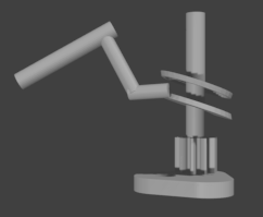
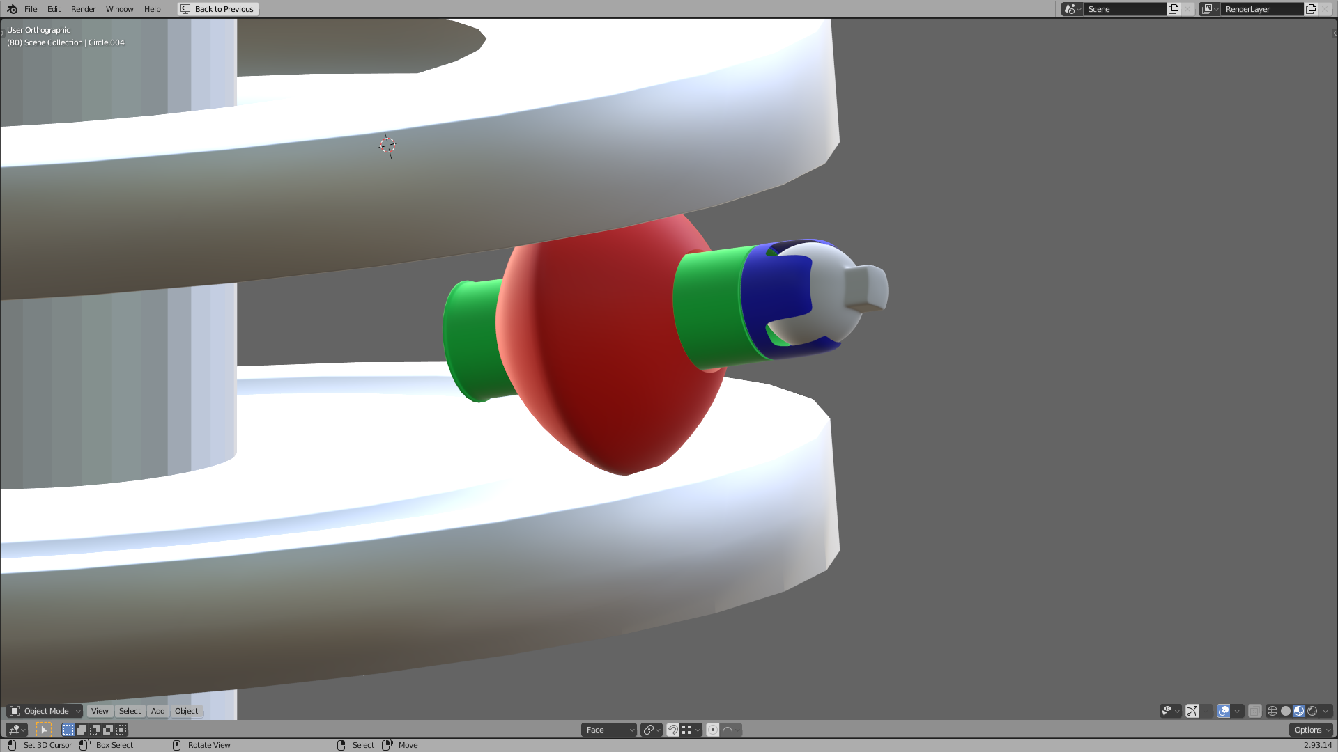
Hi. I’m hoping someone can help me with this. I have a complicated mechanical coupling that I need to implement. As you can see in the attached picture and animation render, I have a cylinder (left-most) which revolves through a small angular range around its long axis. What it’s parented to (not shown, only showing its effect upon that cylinder’s position and rotation) rotates and translates over a small range too. Extending from it are two cylinders (diagonal cylinder and horizontal cam follower cylinder). The remainder includes a thick plate (bottom) that rotates through a full 360 degrees to which the vertical cylinder and the off-axis disks are parented. The gear does not rotate, which I display for inspiration. The model obviously isn’t working perfectly yet. Could anyone suggest any ideas as to how to keep the cam follower trapped between the two off-axis plates? The goal is to control the rotation of the left most cylinder. Note that the model must ultimately work mechanically and I intend to have all parts 3D printed in plastic. The two disks, btw, are not simply flat. Their two mutually facing surfaces (bottom surface of the top disk and top surface of the bottom disk) are recessed just inside the disk’s perimeter so as to have only a point contact with the cam follower, allowing the follower to have some necessary deviation from the horizontal, which you can see will be necessary. I could use rubber bands, the pictured cam and follower or a geared approach (perhaps including more exotic gears than the standard gear shown such as 45 degree gears). The pictured design is not necessarily final. Any mechanical wizards among you? Thx
Ahh… so you not just need an mechanical rig but also wanna build this… after some dicsussion in another thread … i think you have to think about something or clearifiy this a bit… because if you want something like this in traditional building workflows then there are two ways to actually build this:
glueing or welding (with metal) a slanted disk onto an axis and get the wobbleing part because the radius
of this object now changes… or
cut a cylinder in an angle and use the cutline (maintaing the radius) like here Sinusoid( ← now spelled corrcrtly )
And also in the real thing using a ball bearing might be a good idea…
Unfortunately, the distance between the left cylinders and the cam disks changes somewhat due to the motion of their parent and it deviates from the horizontal somewhat. That’s why I like the horizontal cylinder trapped high and low approach, since it can accommodate those to a degree. I’d need to include a rubber band or spring for a configuration that traps the end of the cam follower in such a way, although your approach can accommodate some rotation at their juncture. Quite frankly, I don’t think there’s ANY approach that is both rigid and can hold the cam tightly at all times and won’t result in some backlash (a slight gap between cam and follower at points along the way). But I could include something soft and conformable to keep the motion smooth. Or better yet, make the vertical distance between the two disks non-uniform as a function of rotation angle. But that will require either a careful examination of their gap relative to the cam follower at all points of the rotation or a whole bunch of math scribbling to arrive at a formula for doing so, both of which I was hoping to avoid. Fortunately, Okidoki’s previous solution to an earlier question of mine should make that labor easier, which is why I asked it.
I did after all attempt to summon mechanical WIZARDS, who can use magic and do the seemingly impossible, which could solve the problem more simply.
Thanks again, Clint. You have inspired me to think further on the matter.
Please pay attention, young man. I do want to use all plastic. Cheap cheap. Unfrozen caveman engineer not know metal. Unfrozen caveman engineer not know plastic either. ShapeWays know plastic. Shapeways good. Fired BAD!
Well, when you said impossible, I thought challenge accepted
I read your other thread and realised that I am really out of my depth on this one… but i like a little engineering and i especially like to throw ideas around, so here’s one more for the mix.
That’s a good solution, wizard, which would be appropriate for an industrial manufacturing process. My intention is to make prototype 3D printed parts, and if those work and it all functions as intended, 3D print racks (like a kit built model car) of 10 identical parts each, to mold those and cast my own plastic parts in bulk. Cheap cheap. After thinking about it some more (thanks wizard), it turns out that “making the vertical distance between the two disks non-uniform as a function of rotation angle” should be ideal (a bit tedious, but ideal). That process is:
Edit mode, edge mode, front view, select frame 0.
Right click select the ~horizontal cylinder cam follower object and TAB into edit mode.
Select the lowest and highest horizontal edges on that object. Easy to do in Blender - Just right click slightly below and then SHIFT right click slightly above the object.
Duplicate (SHIFT D) and drag slightly to quickly check that both edges are selected and right click to complete the duplicate.
Separate (P).
In the outliner, join the new object to the rotating vertical cylinder object in the outliner
Advance one frame and repeat steps 2 - 7 for each of the 100 frames of the animation range.
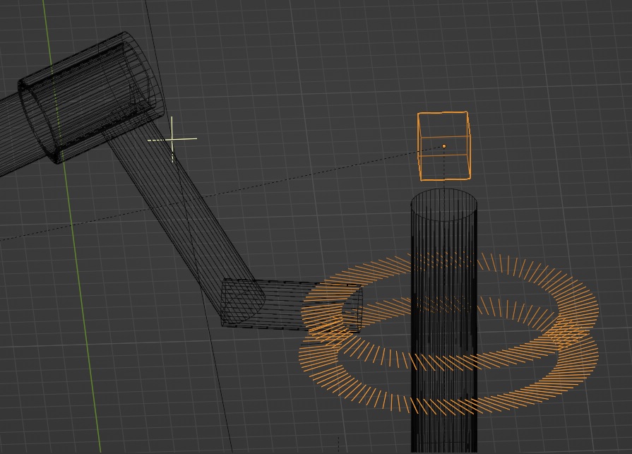
The tedium could be eased with a bit of python programming. That creates a series of ~horizontal edges high and low radiating out from the vertical cylinder, each of which are perfectly aligned to the follower for each frame and rotation angle. It is easy to provide a small gap above and below the follower when finished so as to minimize friction. After a few rounds and knowledge of appropriate hot keys (i.e. some muscle memory), I can complete each step in about 30 seconds, though some of you wizards could probably do each in 10. I’ll show you an animation as soon as I can figure out why my renders of it are grey on a grey background - Blender, which appears to be designed to frighten and confuse mere mortals like me. Are Blender’s creators giggling every time they rearrange the interface? Oops forgot. Need a new topic for that one. I had to do it this way, because these components add to an already complex mechanism that can’t be changed at this point. Ultimate problem solved. Aren’t your talents better applied towards the workplace or making money rather than spending on a mere mortal like me, wizard? Oops (again)! Need a new topic for that one too. Many, many thanks to all charitable contributors!!
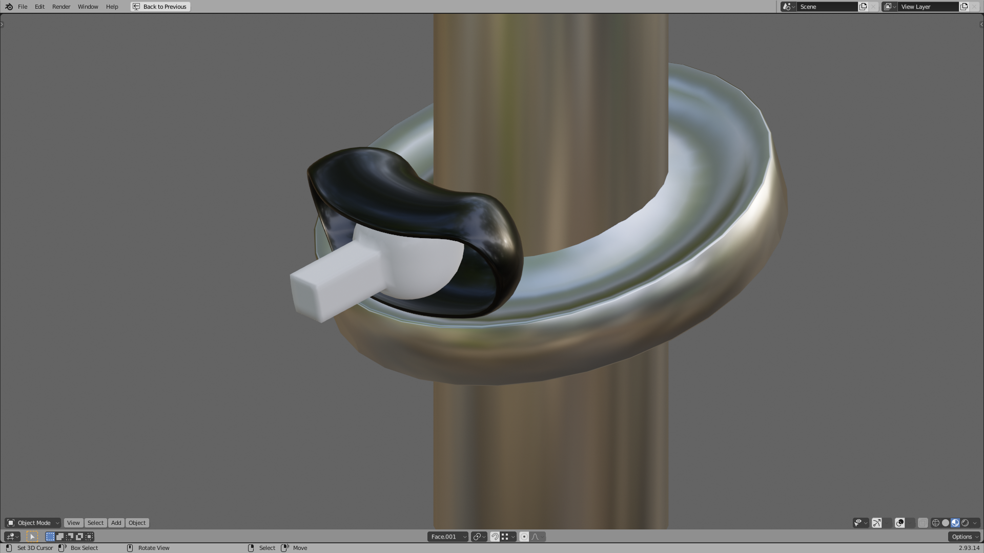
After a little MORE thought, I’ll just give ClintG credit for the solution, since his IS a perfectly viable solution, because he volunteered his time, and because it seems a little creepy to reward oneself. Although, I think if he made the red follower perfectly round (at least in the region of contact), that could serve in place of the blue and grey parts and swivel within its track. Thanks, Clint and other wizards and superheroes who helped.
Actually, my technique does lead to a few slight discontinuities, which you might notice in the jpg. I think what’s happening is that the lowest and highest edges of the follower cylinder stay the same for a while and then suddenly jump to an adjacent edge when the follower rotates enough. To have a pure set of radial lines, it’s best to put a single edge from the center of one end circle to the center of the other. Repeatedly duplicating THAT should lead to a pure set with no discontinuities. It will should have the same angle as the high and low approach.
Wavy gravy. Looks good to me. You’ll notice that the more the arm deflects, the more its motion is towards the vertical, even as its track gets a bit narrower. If it still manages to get loose, I can add a similarly built round lip along the periphery to hold it captive if necessary and a corresponding cut in the follower cylinder. May need a few rounds to perfect what I want, so will probably write a python script and post it here. Set up keyframes manually. Select object to sweep and go! Will post it here when done. If the diagonal arm is driven vertical, there might be a contest between the direction it’s being driven via the circular motion and the direction it’s being driven in terms of changing height (heading back down). Smooth parts and some lubrication should help that.
Will probably try your approach too, ClingG as an alternate. Should only cost a little more. For many or most applications, I think your method would be preferable. But when you want to start with arbitrary keyframes for your rotation angle (i.e. choreography - the heights you need don’t result in simple tilted flat disks), and you intend to realize it in the physical world (3D printers/CNC milling), mine might sometimes be necessary. Good to have two solutions rather than one. Cheers.
Less parts, less plastic, less money… I like it, nice one! Good solution but very complicated, I’m glad you know what you’re doing. I was thinking simplicity, that’s me… could probably just about conjure up a 3D printed plastic ball if I put my mind to it, Shift+A, M, U, W, S ‘Print’
All She will allow me to say is, “I AM.” and nothing more. Mysterious, I know.
I subscribe to suspected Martian pod person desperate to get back home, NASA uber-wizard and inadvertent Elvis impersonator Adam Steltzner’s maxim: “Just… good… enough [will do, although in his case it MUST actually do (and DID)]”.
Here’s the code. You need one AddMe object and one Collector object.
The code will copy AddMe into Collector over frames 0 to 100.
Keyframe AddMe over those frames as desired.
Selecting a simple edge as AddMe is what I use to sweep edges to surfaces
(an edge along the precise center of a cylinder works well).
You can select all (swept) edges then switch to vertices mode and bridge edge loops
to turn the edges into faces quickly.
import bpy
for frame in range(0,100):
bpy.ops.object.mode_set(mode=‘OBJECT’)
Scene = bpy.context.scene
Scene.frame_set(frame)
print(frame)