Constrain a 3 Axis Gyroscope in 2023

Very sorry to ask a question that was, at one time, already answered.

I’m after exactly what ChameleonScales was doing back in 2015, but most of the images and videos referenced are dead, and I can’t reverse engineer the solution in my head.

Goal: Construct a 3-Axis gyroscope in which the central flywheel remains perfectly upright while the whole object is manipulated via the outermost ring.

Just as Chameleon described, rotating the outer ring past 90 Z results in the middle ring flipping around and rotating away from the rest of the model.

There are several ways to make it look perfect UNTIL that 90 Z rotation (parenting, Copy Rotation constraints, Drivers…) but they all break in one or more ways, so far as I can tell, and I can’t figure out what is meant by,

rotate the piece that has its joint on Z so that it goes on X, then parent it to an empty and add the constraint to the empty instead of the piece

Which constraint? A Copy Rotation or a Child Of? Wouldn’t rotating the thing 90 degrees leave the poles of the gyroscope incorrectly aligned, or do you rotate the vertexes in Edit mode, then counter-rotate the mesh in object mode?

Without reading anything in that thread, just looking at the pic, I would do it with IK with rotation enabled:

untitled.blend (111.6 KB)

We have a three chain IK, parented to our control bone (to which the outer ring is parented.) The last bone in the IK chain doesn’t affect anything, it exists just to give some allowance to our IK (since our inner ring does need to rotate, it just needs to rotate within certain bounds.) I use IK locks to prevent the rings from rotating the wrong way.

Note that there are four solutions to the problem: middle and inner rings can be rotated 180 degrees and still solve it, either or both. So if your plan is to use with some asymmetrical, you’ve got to define which way to act, and the way constraints work, it’s not going to act on how it solved it last frame. ITASC IK solver on simulation mode might work for that, but be aware that there are issues involved with that (like when scrubbing the timeline without starting from 0) that are similar to issues with physics: once you tell it to pay attention to the last frame, it needs to know the last frame.

1 Like

If that’s the only solution, I’ll look into it, but I’m hoping there’s a method that doesn’t involve rigs and bones. I just want to with with the final result in Object mode without having to jump into Pose, (or having to run a Physics sim, Lord save us).

Further research on things like, “Constraint flipping,” and, “90 degree constraint/driver rotation,” suggest that Blender’s handling of gimbal locks is to blame, but I can’t wrap my head around any of the various “solutions,” passed by various sources.

Downloading and fiddling with bandages’ proposed solution, it seems like things still occassionaly flip, or at least the rig spazzes out every once in a while.

An ideal solution would omit rigs entirely, as they require either jumping back and forth between Pose and Object modes, or creating an intricate system of Empties and “Parent Of” constraints so that Poses can be controlled in Object mode.

Or hooks, or vertex parenting, or whatever it is that lets an Object move a Bone. I’ve had a little cider tonight.

I’d strongly recommend getting over your bone reluctance if you want to animate in Blender. It’s not that hard to enter pose mode (I “ctrl tab” with armature selected) and if you’re animating, you basically never need to leave pose mode. Restricting yourself to object animation is artificially limiting yourself. If you’re most comfortable with object controls because that’s what you’re used to from a different application, well, Blender is different, and if you want to use Blender, you’re best off embracing its differences rather than resisting them.

But, here’s a version that uses drivers on objects instead (and an object constrained empty to get the values for those drivers):

untitled1.blend (141.7 KB)

It’s still going to flip, because there are still four solutions to the problem, and the solution you want is probably the one continuous with earlier frames, while constraints and drivers don’t know about what happened on earlier frames.

1 Like

Mirabile dictu, I think I’ve managed to establish a workaround. Have a
.blend (984.0 KB)

Mind you, it’s a workaround. It only seems to work, but doesn’t actually correct for the underlying issue. You can still get things flipping backwards if you’re not careful.

The two main issues are Gimbal Lock (or how Blender copes with it), and the fact that you want the innermost piece to act semi-independently of the outer frame, so everything in the middle is sort of serving two masters.

Given that the previous thread discussing this issue suffers from broken links and missing image files, I’m going to go through the setup in painful detail below. Fair warning.


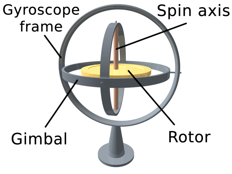
First, let us establish the “anatomy of a gyroscope,” courtesty Lucas Vieira of Wikimedia:

What I did:

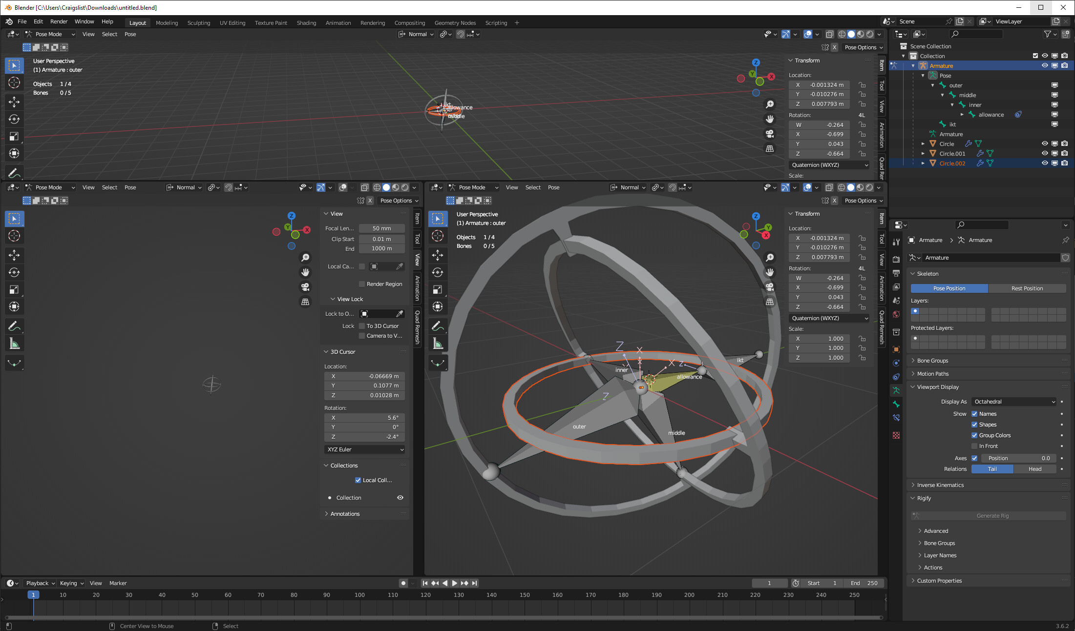
Model the Frame and Gimbals such that they are NOT locked. Establish your outer frame, rotate the outer Gimbal 90 degrees along its rotational axis, and rotate the inner gimbal 90 degrees along its rotational axis relative to the outer gimbal.

That step tripped me up, because I originally modeled everything as a flat series of rings. I basically made the most locked up gimbal you possibly could, which made everything afterwards more difficult.

If that’s hard to follow, I’m saying, “model it so it looks like the picture above,” adjusted for whatever hierarchy of axes you prefer. VERY IMPORTANTLY, make sure you APPLY ROTATION to all three rings and the central Rotor.

Before you get into parenting and constraints, we need two empties. Place the first empty at the very dead center of the rotor (which, if everything else is symmetrical, is the very center of all other meshes too). I’ll call this the Core.

Place the second empty outisde the Outer Frame, dead center on the Rotor’s Spin Axis (see image above). I’ll call this the Pointer.


Parenting:

Outer Frame: No parent. You’re meant to end up using this to move and reorient the “whole thing” around in space.

Outer Gimbal: Parented to Outer Frame

Inner Gimbal: Parented to Inner Frame

Rotor: Parented to the Core.

Core: No Parent.

Pointer: No Parent.


Constraints (listed as stacked):
The proper configuration of your constraints will vary according to how you designed your gyroscope. What follows assumes your build matches the photo above while at rest.

Outer Frame: None.

Outer Gimbal:
Locked Track: Target Pointer. Track Z. Lock X
Limit Rotation: Y and Z (Min/Max 0). Owner is Local Space.

Inner Gimbal:
Locked Track: Target Pointer. Track Z. Lock Y
Limit Rotation: X and Z (Min/Max 0). Owner is Local.

Rotor: No Constraints

Core (Empty):
Child Of: Target Outer Frame. UNCHECK all Rotations.
Damped Track: Target Pointer, Track Z.

Pointer (Empty):
Child Of: Target Outer Frame. UNCHECK all Rotations


Drivers:
Rotor: Rotation Z = frame* x (where x = speed)
This frees up the Rotor to “Spin” without affecting orientation for any other parts of the Gimbal, and makes life easier if you need to do something to it.


Now you have two separate controls for your Gyroscope. The Outer Frame is the direct manupulator. Tranlsate and Rotate XYZ anywhere in your sceen, and the central Rotor should not be visibly affected by it.

The Pointer Empty, then, allows you to manually reorient your Rotor if you don’t want it pointing in its original direction. It wouldn’t be physically realistic to change that direction over time, but options are good to have.

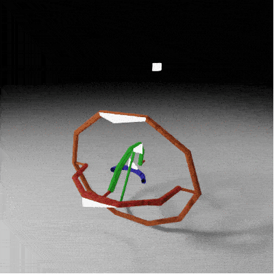
Here’s an animation test of the finished result. I’ve lopped the Gimbals and Rotor in half, and added little glowing points to them so you can see that they don’t spontaneously flip or reorient. I also parented a little emitter to the Pointer empty so that can be observed as well.

GimbalTest


About that Gimbal lock…
I never allow the Pointer to become centered directly over head of the core, which is where it was when building and constraining everything.

That point causes a lock, and I supsect if you imagine the five other “cardinal points” (direct below, direct in front/behind, directly to either side), they would too.

If you downloaded my Blend, you’ll notice a third Empty I never mentioned, because it’s optional. I put a “Reference” point dead center on the Z axis directly above the Core. I then put Limit Distance constraint on the Pointer, set to Outside, targeting the Reference.

That prevents the Pointer from landing on or passing directly into the lock. It’s not a flawless solution, but seems to work well enough. Replicate it for each of the “cardinal points,” and you would at least avoid those most obvious locking points. If other locking points exist (since there are two Gimbals, not just the one), you’d have to find a way of keeping the inner gimbal clear of them, which is overkill on top of overkill.

I sincerely hope this helps someone at some point in the future when all my links and images are broken…

Thank you for the Driver-bound version. I appreciate that you’ve taken the time to offer some alternative solutions to my specific challenge.

The project this arose from involves a great number of simple objects, but almost no armatures. The gyroscopes, which will be numerous, are meant as an afterthought; just a bit of dynamic detail that looks after itself. Getting them to work passively in Object mode was therefore desirable.

I do not have an aversion to pose mode, and yes I know the hot key to switch into it. I have no substantial experience with other dedicated 3D programs. As I said, I would implement an armature if no other solution could be found.

Feel free to unfollow this help thread, as I seem to be annoying you. I’ve only tried to be clear about the specifications of what I’m trying to achieve.

I don’t appreciate having my criteria brushed off because you’d rather I just do it a different way, nor do I care to have to justify why I’m concerned with a specific objective.

Hi,
I found the file I used this for back in 2015 (you can open it in Blender 3.6) :
Gyro_packed.blend (806.8 KB)

If you grab the outer ring, you can rotate it any way you want, the other 2 rings will rotate to keep the central piece in place.
The setup is quite simple (just a couple of “Copy Rotation” constraints) so I don’t know if it addresses all the issues you have but if you want a more advanced one, tell me what kind of controls you want and I’ll give it a try.

1 Like