Now I’m working on Anim about a real terrain with a real coordinate system
made with topography, so I’m using UTM coordinates that frequently go around
1.000.000, 1.000.000, 500.
so i have 1BU=1 meter, have sucessfully made a huge mesh with the terrain, UV mapped
and the mesh of the to be constructed high way, everything was fine (since i almost finished)
my problems arises when try to place small objects, less tan 1m some times the X,Y axis can’t get more than 10.000 units so the objects ‘disapears’ when try to move just a bit.
that small problem is annoy me , also the small movemets of these objects seems ‘bumpy’ i can’t get a shooth mevent to get a good placement.
so any one knows how to make the cordinate system more ‘bigger’ ?
one thing that i can’t do is transtalte it to 0,0,0 just because i loss interop with designer’s CAD files.
i tried it again and i cannot place in N-transform a value grater than 10000?
don’t know how you got that high value for location ?
unless it’s been changed in blender the limits i gave you are the maximum values you can play with ?
can explain how you did that - i mean to set these values so high ?
another thing is that look in veiw properties your clip end is at 10000
so anything outside won’t be shown ?
hi, i guess I should chime in. Organic is correct. You have, in Blender, 7 significant figures for the location of something. (this may change with 2.5, but is current for 2.47). For mathematical reference look up the terms accuracy versus precision or wiki reference page
To use a simpler example, suppose we had 3 significant figures. We could then express a number range of:
1.000 to -1.000
10.00 to -10.00
100.0 to 100.0
1000. to 1000.
The precision (number of digits to the right of the decimal point) varies based on the grid spacing in our case, but we still only have so many “places” to put numbers in. In the example above, we would use a grid spacing of 1, 10, 100, and 1000. Put another way, Blender can store the location of a point to within 1/1000th of a Grid Spacing. You can even go higher, but you lose digits and blender will start to round to the nearest 10, the nearest 100, etc as you increase.
OP initally wanted 9 “sig-figs” as my son likes to say, which we currently dont have.
blender has 7 digits number for let say location or other variable
but i you look to the panel in there is a number like 1 milliions and then after the dot 0.000 this is 10 digits numbers
i just open an existing file with 2.48
i tried to change the division to 100 and then go to n Panel and try to enter 1 000 000
and it comes back to 10,000
so how was thie 1 millions number tnered there in this field ?
is still cannot do it ?
is there any modification in sight ot increase the preicsion of blender
like you said Papismurf to go to 9 significant digits it would a lot easier for lot’s of people mostrly involved with modelling mechanical architectural things
another thing Papismurf when you work with script i waht is the max digits precision inside script s ?
i think this is a lot more precise then inside blender per say?
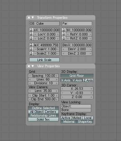
as he shows above in the View Properties panel, by changing Spacing to 100, he is able to enter 894,031.8 as a location for the X coordinate fo the 3D cursor. Sadly, spacing only goes up to 100, so the limit is a million.
Python does automatic type assignment based on what you set a number to and following the rules of division. See Python.org for discussion on the number types supported and their accuracy.
Ton is aware of this limitation and has said it is on the slate to be changed.
i tried th file with the big number that i downloaded and it show digits that are not precise
in the sense that you can put more digits than thre real precision of blender
so i think the format is not working propely
there is another thing here that is confusing how do you relate the scale of the drawing and the grid spacing?
if you take 1 BU = 1 Meter you have to leave the grid at div = 1 to get the limits 10,000 down to 0.001
but if you change the grid it will change the precision at which you wokr
so you got be bery carefull here to remember that?
but i guess the enxt version will correct this hopefully
any idea whene we should have more digit which version 2.5 ?
Coordinate limits are definitely an annoying limitation to Blender, but there are some work-arounds I’ve been able to use.
First, I’ve done some Python scripting that will transform a project from its design system (in your case UTM) to coordinates closer to the Blender origin.
For example, I’m writing a script that imports animated traffic simulation data from Vissim into Blender, showing automobiles, turn signals, brakes, and traffic signals. The coordinate system we use for the design and the simulation is generally either arbitrary or state plane, neither of which are friendly to Blender. So my script evaluates the ‘bounding box’ of the simulation/project data and centers it at 0,0,0 in Blender and, if necessary, scales the data down. It then stores these translation/scale factors in an exterior project file so it can be used for placement of other objects.
I’m also writing a library of civil engineering scripts for Blender that will allow proposed pavement via LandXML alignments and profiles, use of station and offset coordinates, and other things. Email/PM me if you’d like me to let you know when these projects are available.