I’m lost…
I’m a total beginner in Blender and I’m stuck/overwhelmed/swamped … Please tell me if Blender is the way to go. I need to find a way to solve following issue with the correct tools.
I appreciate any support. Thank you.
What I want to receive:
A landscape that can be 3d printed. → export file format: stl / obj / 3mf / step for the slicer software.
What I try to do:
I want to use a landscape (stl file) with the low res data as a base model. At chosen areas I want to exchange the low res data with the high res geotiff data
Given data and sources:
stl file with medium/low resolution by touchterrain
geotiff with high res by local gov site.
Unfortunate detail: the gov data ends at the frontier. The desired mountain area is at the frontier…
What I have done so far:
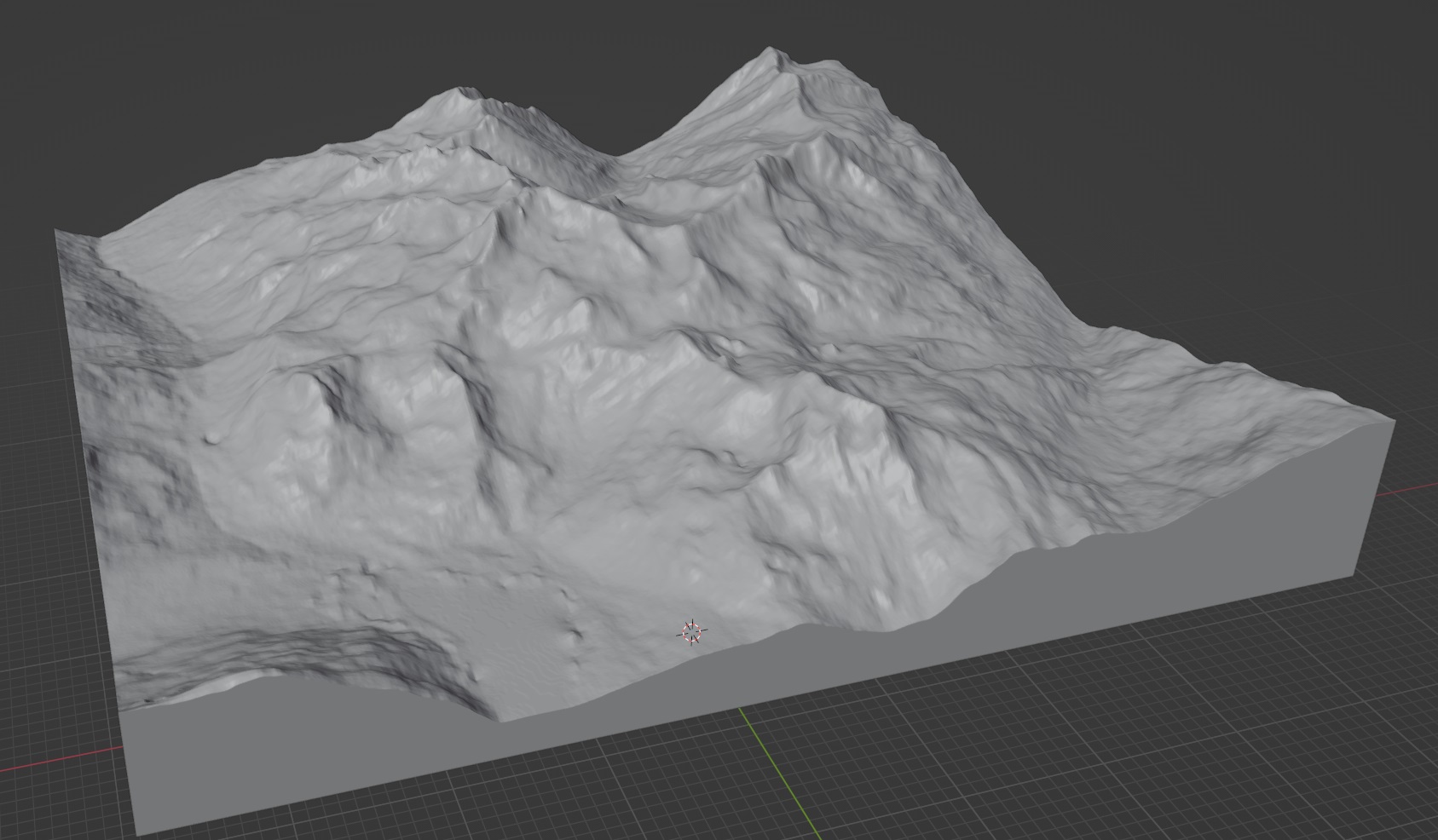
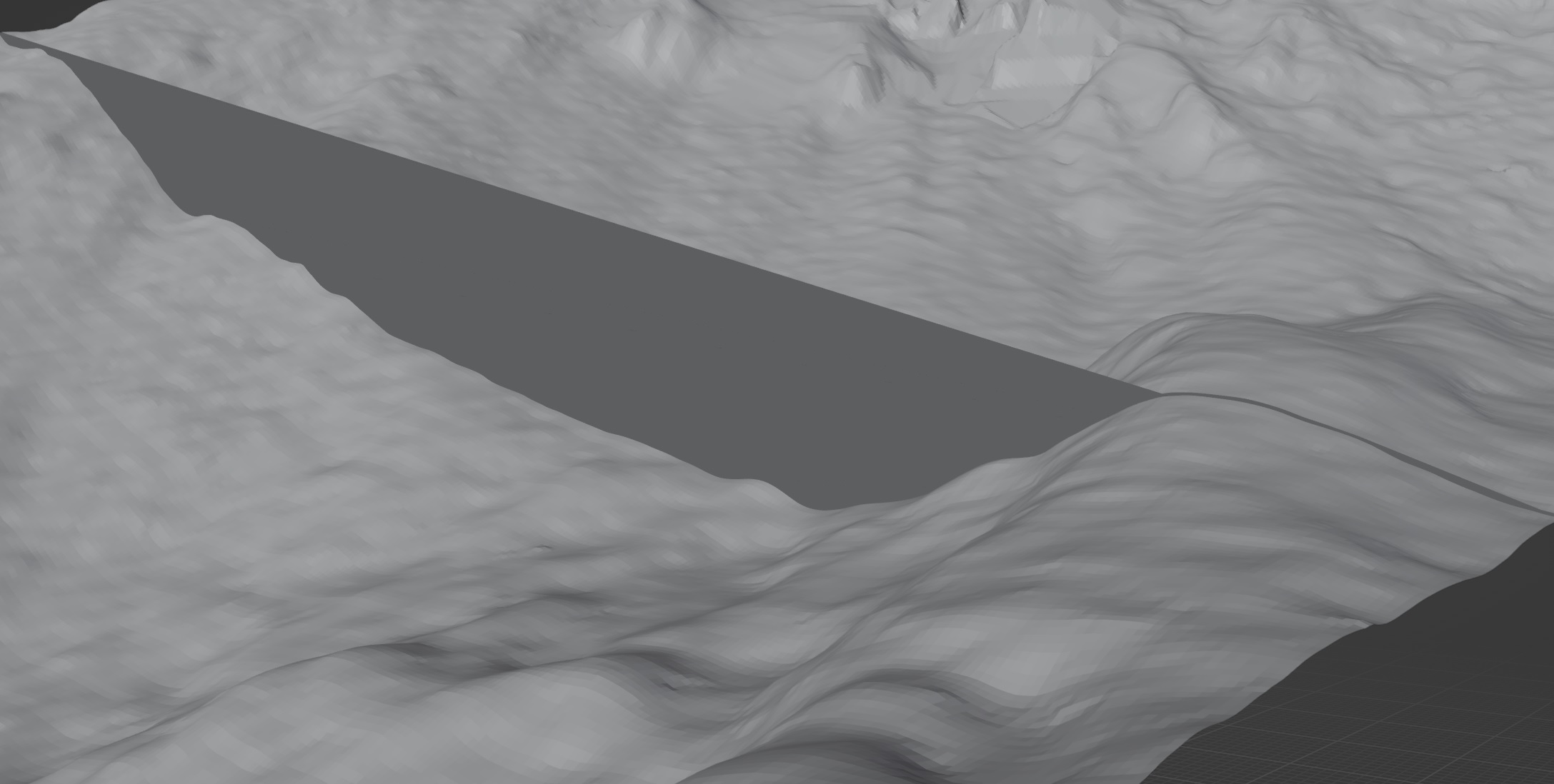
I imported the stl (low res) which gives me a 3d model with a heightmap on the top face. yeah!
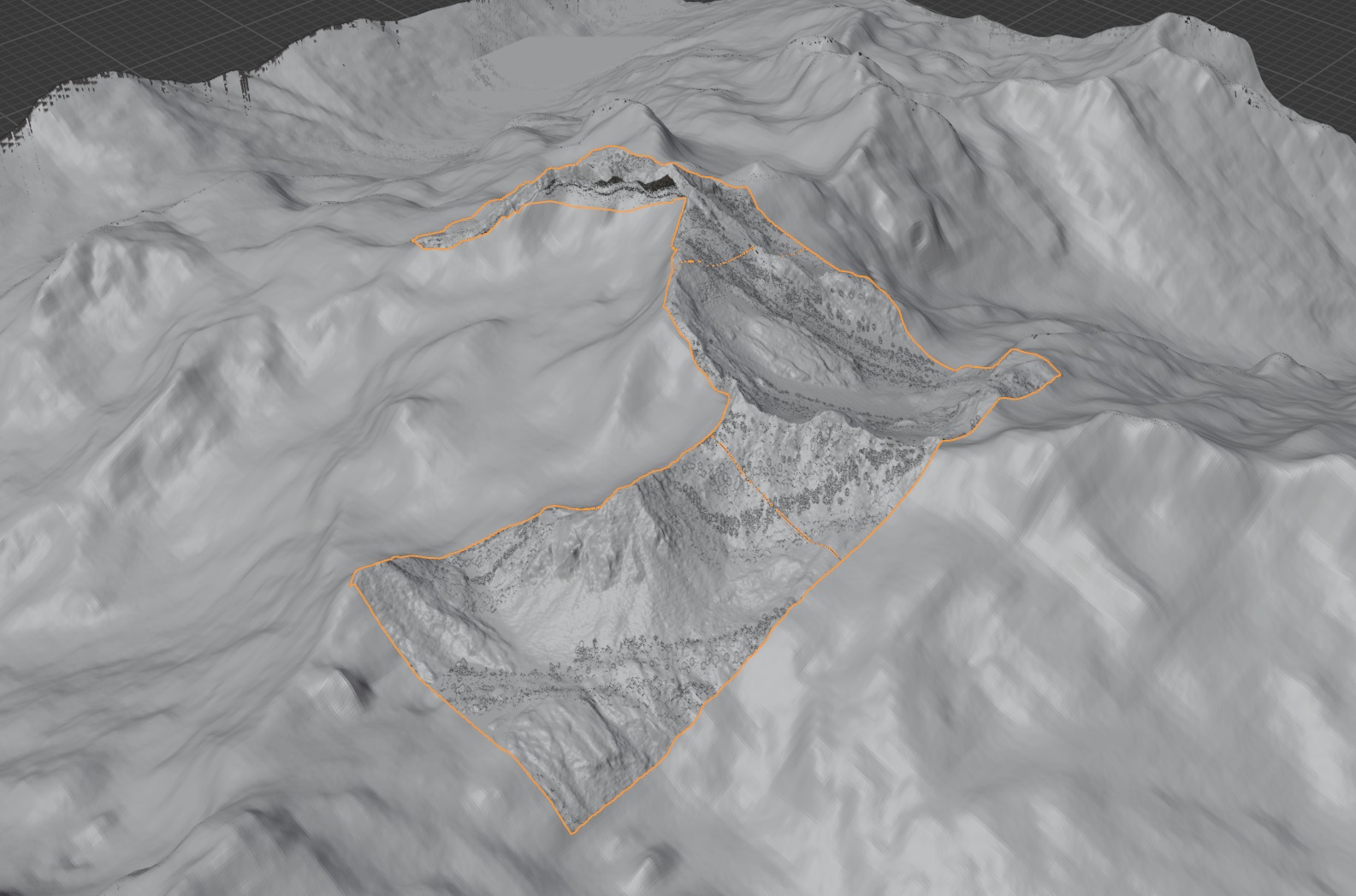
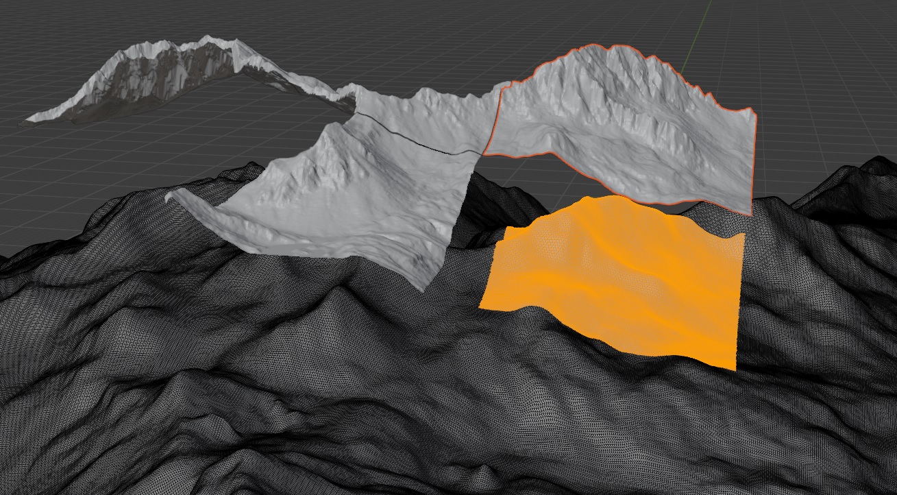
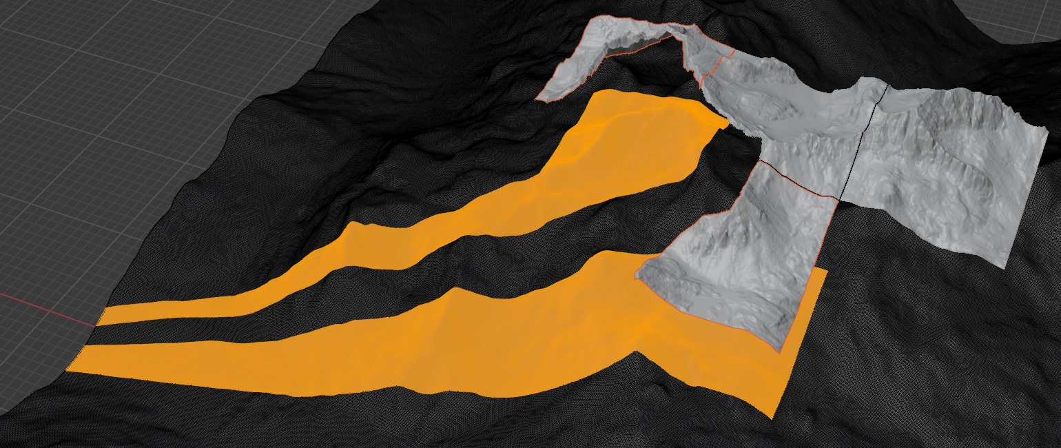
For the mountain peaks I imported the high res geoTIFFs. I used BlenderGIS to import the geotiff which creates meshes. I aligned the data manually as good as I can.
What I think would be next (is this correct at all?):
The geotiff tiles have a size of 1km x 1km. I used for this example 3 files. Between the meshes is a gap of exactly the same distance as the mesh grid distance.
I want to
connect the mesh edges (new faces?) to get 1 mesh. In this case it would finally create a L-shape mesh. I don’t want to move the tiles the gap distance because it would change the real distances.
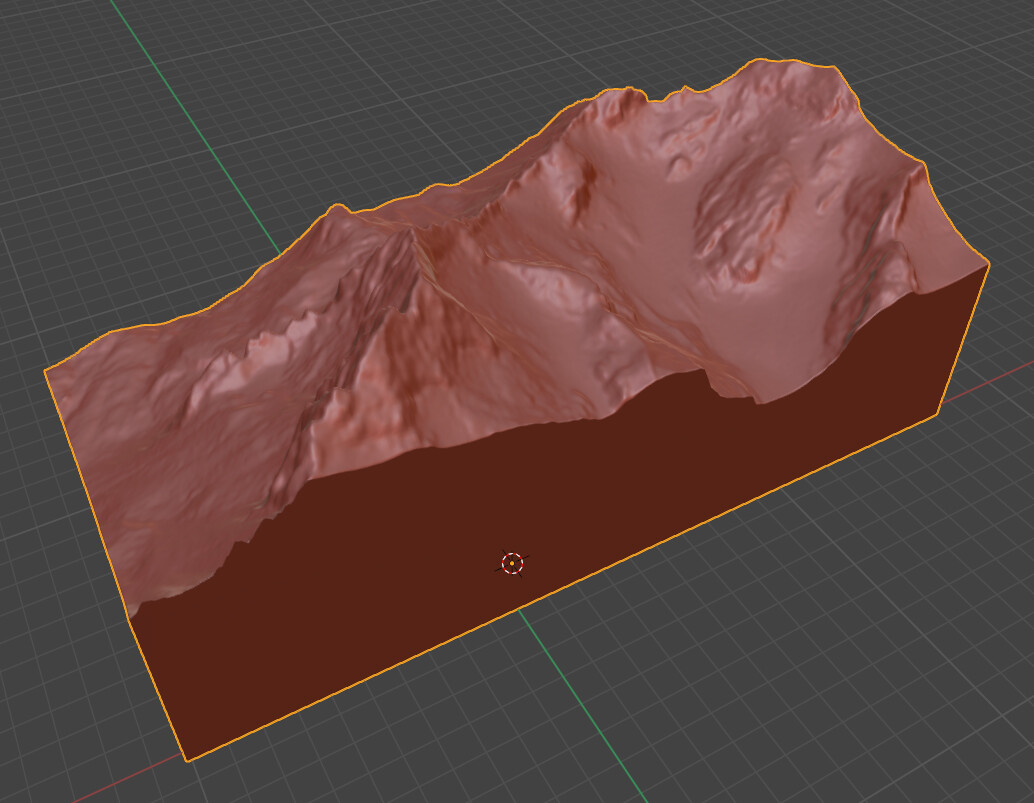
create a 3d model (extrude the meshes in z direction to level 0m ) to get a model like the stl in the first image.
cut and replace the low res model → L-shape model in the low res model
merge the los res and high res models → 1 combined model
smooth the vertical walls from the model interfaces with a sculpting tool.
Is my approach reasonable? if so, how to do this?
Fails so far:
at step 1:
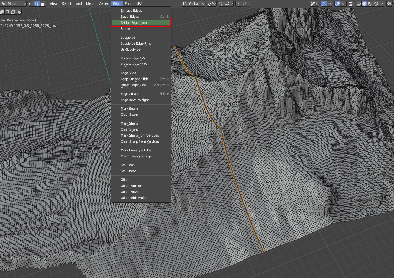
I tried to select the edges of 2 meshes next to each other and create new faces. But that didn’t work.
It creates too many faces and doesn’t connected only the closest lines.
at step 2:
I don’t know how to extend the mesh in z-direction to create the block. Can’t find the tool for that. It sould have a flat bottom and flat sides.
step 3-5 I didn’t try but it seems to be easier because I found a lot of tutorials to do that with modifiers …
Oh man. What a mess…
Thank you.
[[I’m sorry for the language fails but English is not my first language.]]
Did you join the two meshes together before trying to bridge between the edges? You must join them together… Object Menu > Join (or Ctrl-J)
A messy connection is to be expected. The high detail will have more vertices so you will get multiple to 1 connections. You can (In Vertex Edit Mode) do a right click > Smooth Vertices a couple of times. I would look for the missing high detail maps before doing too much join fixing. Perhaps through the websites of the govt over the border.
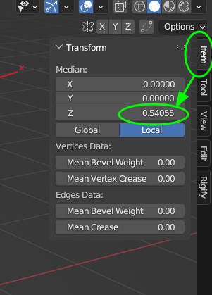
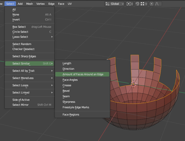
Select the outside vertices. One way is Select Menu > Select Loops > Select boundary Loop. Extrude that outer edge down. Scale it to zero on Z. S, Z, 0 is the quick way. Snap it to zero or use the side panel …
If you have a Boundary Loop from 2 you can Shift-D Duplicate it, then Mesh Menu > Separate > Selection. Back to Object mode and select the new object. Edit mode and extrude up and down. That will give to a mesh to do a Boolean cut to make the hole to fo the swap out.
Covered already.
If you extrude the boundary loop it should be smooth…
To gain more trust (AKA be able to post more images at once) spend 10 minutes giving likes and comments over in the Artwork section. Or you can post an image per comment, or share the images on the cloud… If a automated bot appears follow its instructions to gain higher trust ranking.
Some of the things I mentioned (vertex smoothing, boundary selection) are good to have on your own Quick Favorites Menu. Once you see the item in the menu, right click and select Add to Quick Favorites.
i thinkk you have to cut out the area where you want to insert the highpoly… expanting your cutout by one vertex and edge select soem borders almot one by one and file them to triangulate them or use the bridge tool but not for all at once…
I tried your suggestions but it didn’t work.
Maybe the imports of BlenderGIS are broken or differ in an important detail I don’t know and I should change an option. Some actions did work for the imports if the tile has no missing data (full square mesh) because of the frontier area.
@Matakani
1.:
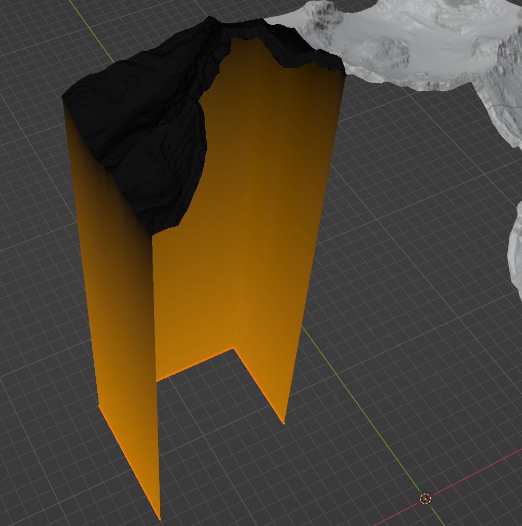
I joined the meshes but the result is not good and doesn’t work with “smooth vertices”. The wrong faces are changing but aren’t created between the 2 meshes. Large vertical faces are the bad result.
The meshes only get connected at the outer edge points. Mainly the faces are created between the edges of the mesh itself giving the large vertical faces.
2.:
select boundary loop or loop edges doesn’t work. (I followed the steps of the blender manual)
I don’t know how the select loop function works in the background but it doesn’t work with the GIS mesh that is not a full square tile. The steps 3-5 can’t be done with this open line.
A fully square mesh seems to work with select loop boundary and could be used for the scaling to Z0 trick.
I got the idea and think with a duplicate of the edge before scaling to z0 would be a good way to do the cutouts. (true vertical sides)
The “cookie cutter” :
@oo_1942
The posted vid shows a good solution. But I get an error when I select “Knife project”: no other objects have boundary edges to use for prjection. I also tried it with a square tile but still the same error message.
any alternative suggestions? I could upload a non square tiff mesh or the .blend file
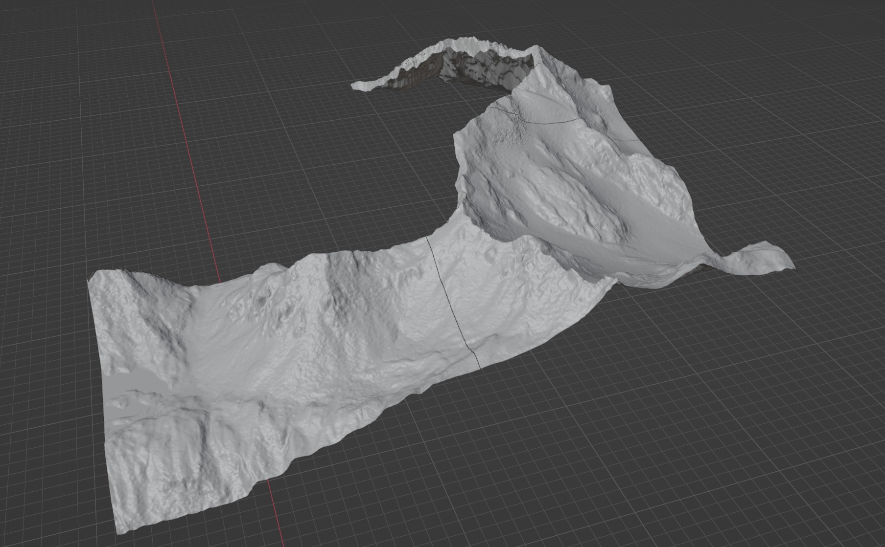
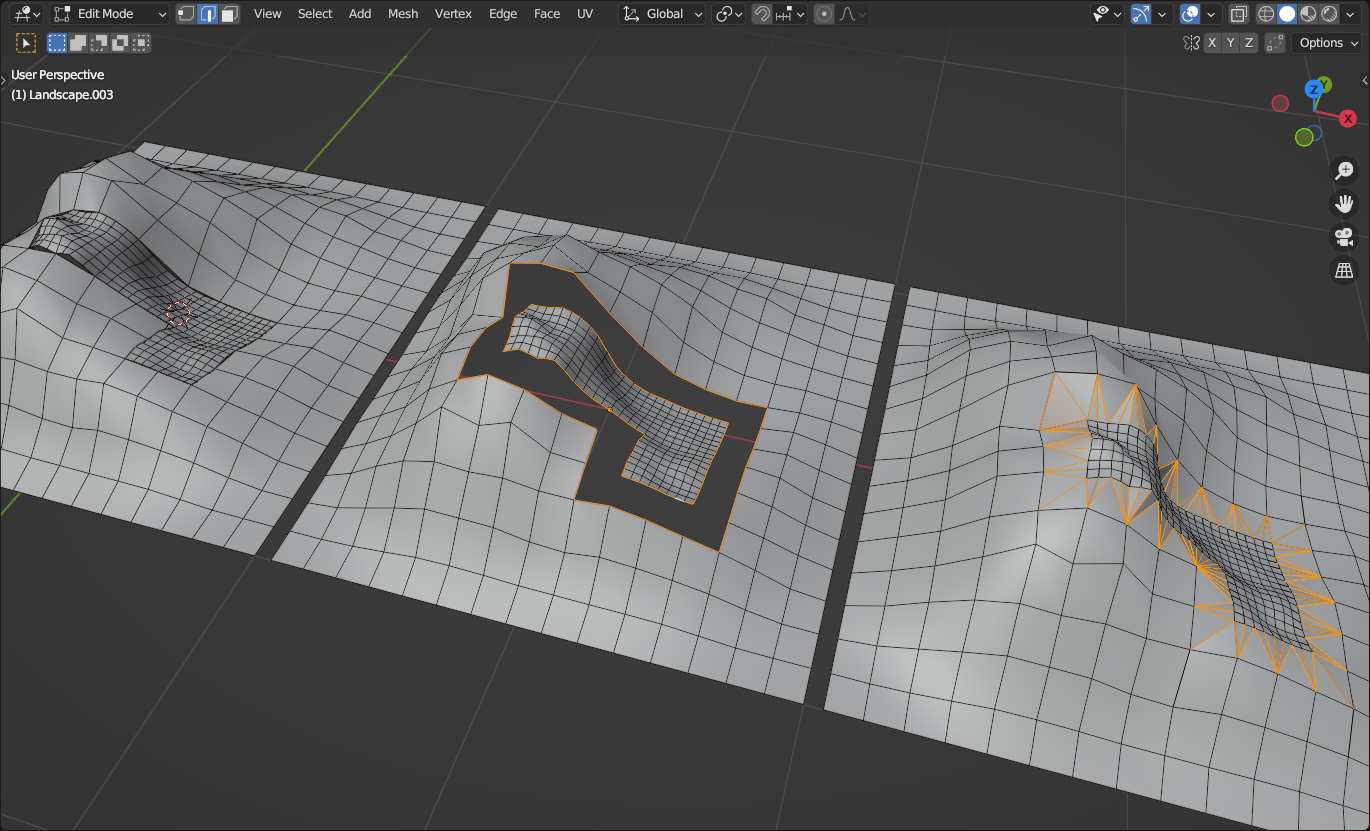
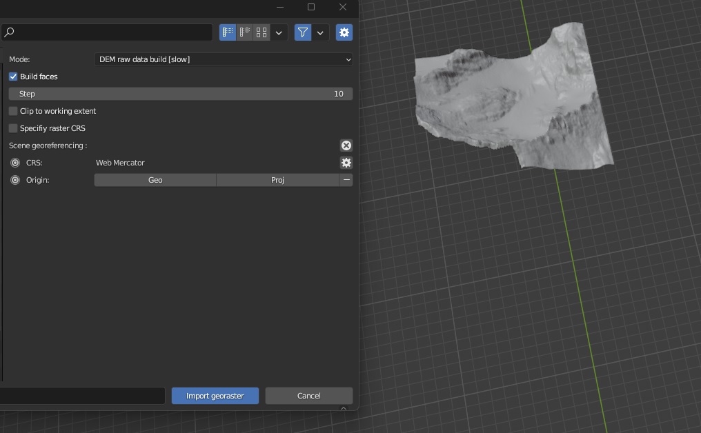
geo tiff imports by BlenderGIS (raw DEM): two meshes with square (full size) shape and the open (frontier cutout) shape
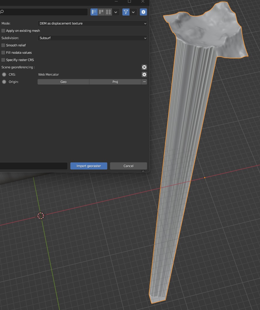
geo tiff import by BlenderGIS different import option (displacement): additional mesh moved to the side
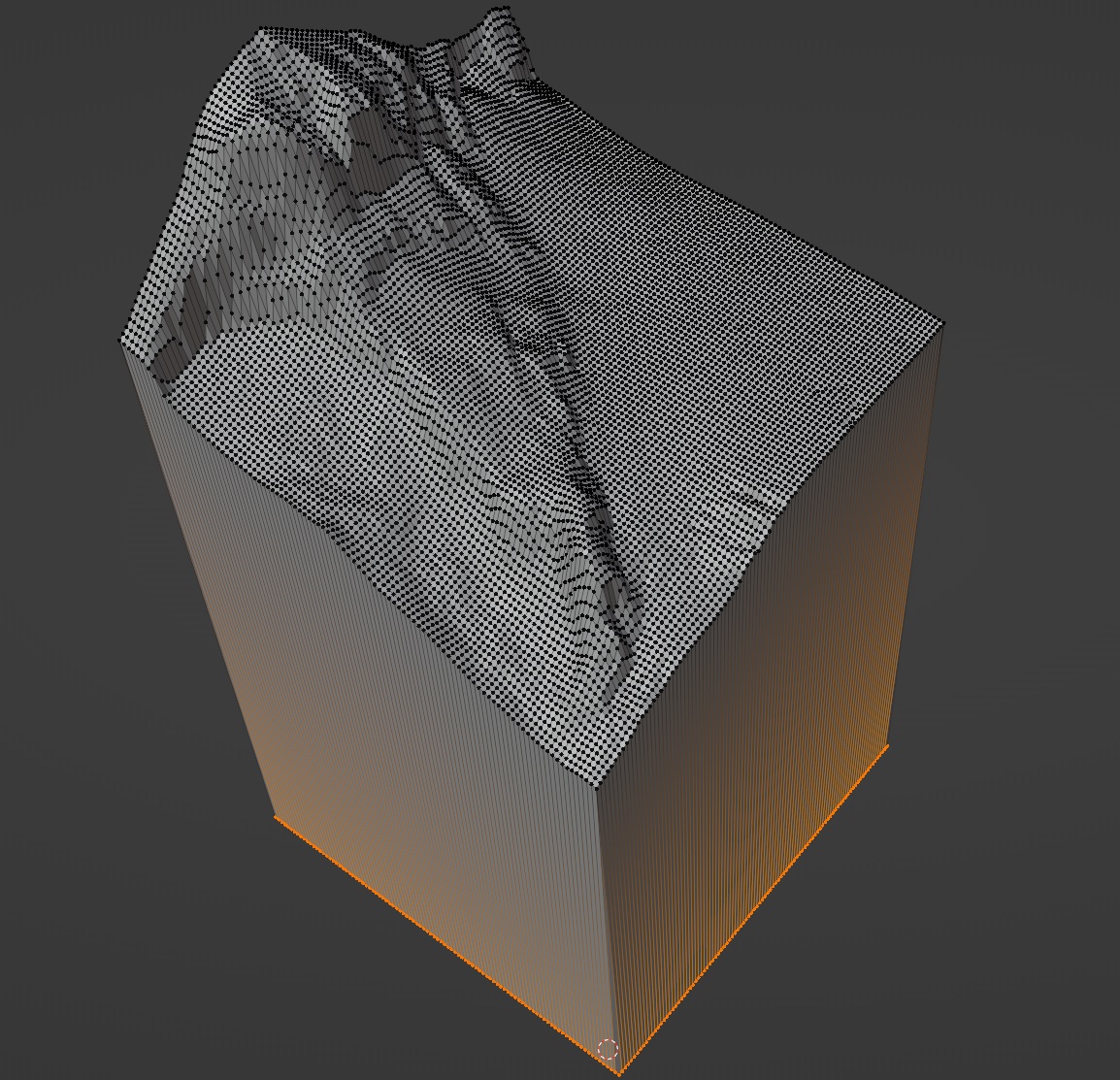
Ok. The video shows a different flow than I tried and it worked with the square mesh (image below). thanks.
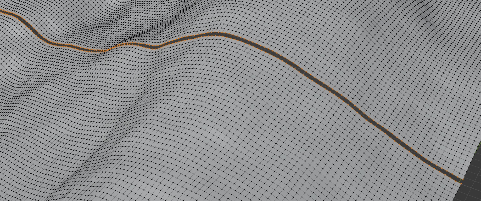
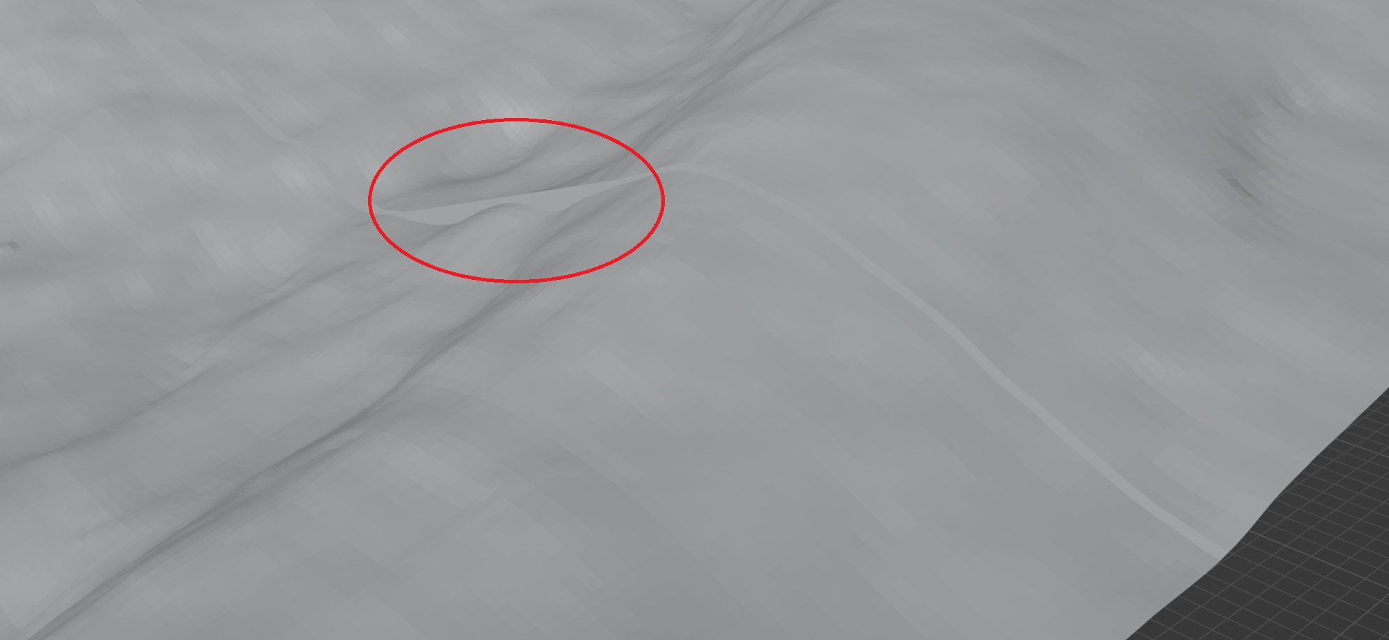
But the frontier mesh is somehow broken. the Knife Project selects additional vertices
Some additional images which maybe help to understand the technical issue:
I make a lot of STL models for cnc patterns. I have been making and selling custom cnc patterns for over a decade.
I am also a dedicated horrible modeler. I know how to do it right but I don’t have the patience to do good topology. I much prefer to do it quick and dirty. So I have times where I have to combine discrete objects into one model and my topology is so bad it is nearly impossible to do so without remodeling everything over again.
A tool in the toolbox is to create a grey scale height map image of all the piece parts. This is not optimal and should only be used as a last resort but it will give you a unified model result that ignores (mostly) all the bad topology.
Again, last resort but 9 out of 10 it gives a result. lol
Use a lossless format for the height map for best results.