I’m trying to create a rational Bézier curve (actually an approximation of one). To do so, you need to create a normal/ordinary Bézier curve (in space) and apply an perspective projection to it. That means that each point of the curve is projected towards the origin.
Between the normal Bézier curve and the origin one adds a plane, so that the Bézier curve is actually projected onto this plane (this projection onto the plane is your rational Bézier curve).
How to create a vertex at the intersection of a line and a plane? Is there a ready-to-use function for this, or is it possible to create a vertex on a line, and slide it (along this line) to a certain height (z-value)? That would be all right since I know the planes z-value.
How to create a vertex at the origin? The way I do it now seems a little cumbersome – creating a circle (with 3 sides) in the plane z=0, deleting two vertices and moving the third one to the origin.
Can I make my plane a little translucent (in the editing mode)? I set some material properties, but without result.
When I first select a vertex, and then Shift-select another, is there a shortcut to un-select this last vertex (except for Shift-clicking it again)? The Ctrl + Numpad Minus deselects all – is it possible to configure this somehow? The thing is, I’m looking for a fast way to draw all those lines you see in the figure above.
Is it possible to display the actual control polygon of a Bézier curve? For me that would be more useful than these handles that show up.
@RickyBlender, you mean start with a poly line (don’t know where I can find such a line by the way, in the menu Add → Curve I only have things like Bézier, Circle, NURBS, Path)…? Then I won’t get a rational Bézier curve in the end. I am using Blender 2.62 by the way (on Linux).
@Ricky, a rational Bézier curve is a perspective projection of an ordinary Bézier curve that is defined in a higher dimension (just one dimension more) onto a plane. This sounds a little abstract, so here is an example. The easiest version would be a 2D rational Bézier curve (on a plane), which is the projection of a normal, ordinary, Bézier curve in 3D space.
This is exactly what you can see in the figure in my first post. In the top there is the ordinary Bézier curve (in 3D space), from which some lines emanate (towards the origin). Then, someway between the curve and the origin I added a plane (so a 2D “space”). Every line intersects with this plane (each line “creates” one point in this plane). If you take all those created points together, that would be the rational Bézier curve.
do you need bezier curve here or you can work with poly or spline curve?
i mean in blender you can easily convert from bezier to poly to spline anyway!
also you can convert from curve to mesh line or mesh to curve !
now here we are talking about a 3D curve bezier or other not a 2D one ?
another problem here is you cannot show 4D lines in blender only 3D !
how do you deal with that in blender ?
there was a script last week on how to add a bevel curve between 2 objects in python forum !
my guess is re open a new thread in python forum and ask for a script to do this
and reference this thread here !
also for a bezier curve you can see only the control points not all intermediary points!
but if you use poly then yes you can see all points !
i think it should be possible with a small script and other peoples might be able to help on this task!
now don’t know what this would give with 4D bezier
never work with that beast before !
can you give example of 4D curve cause right now in blender we don’t really have 4D curves only 3D
so you would have to define your own math model for a 4D curves parameters for using in a script!
The lines between origin and curve points could be done with vectors or lines bezier too !
depends how you do it !
but i don’t have script example of 4D bezier lines only 3D !
i mean which one do you prefer here ?
vectors might be easier to work with mathutil anyway !
@Ricky, thanks for yet another answer! I’ll look into the Python stuff.
It would be quite difficult to depict a 4D curve :D. However, since I’m familiar with the mathematical background of Bézier curves I could give you an expression for a 3D rational Bézier curve (but not sure whether that would be useful). Actually you can think of it as an ordinary Bézier curve, but with weights for each control point (the higher the weight, the stronger that control point pulls on the curve).
Mind you, the idea is not to actually create a rational Bézier curve. I only want to create something like in the Figure above, that shows the process of creating one.
but on screen you could see only the 3D rationel bezier curve onto the plane !
not the original 4 D bezier which cannot be seen on 2D screen i think !
and for the script i mean if you start from a 4D bezier then you will need to somehow defined the points with an algo for a 4D bezier to start with i think !
I don´t completely understand what do you will to achieve, but maybe thisway:
Put the cursor at 0;0;0 and create the bezier-curve. Tab to edit-mode and grab the curve to z-direction where you want it. Go to object-mode and convert the curve to mesh (alt c). Back to edit-mode, select all the vertices and duplicate them (shift d). Set the pivotpoint to cursor (0;0;0) and “fake-extrude” duplicates and scale them to 0 (e-> esc-> s-> 0). If needed remove duple-vertices (w -> remove duplicates) and there you have the radius´s. Now set the cursor to the high in z-axis where you want to create the plane and create them. (See N-panel-> cursor location). Now select all the radius´s and subdivide them (ctrl r). From N-panel you can see the level at which the vertices appears and move them to the plane level. Possibly it is needed to use edge slide tool too (w-> edge slide). Now the “rational bezier-curve” is located to the plane.
In editmode by the header you find “limit selection to visible”-icon. Tick it off.
Ctrl z is undo in blender.
You can choose any one “row of vertexes”, separate them to own object and convert them to curve (alt c) or vice versa.
@Marksto: Yep, sounds like it! But I’m not that experienced with Blender yet, so there are a couple of things I don’t understand…
When I select all vertices, the edges get also selected. Is it possible to only select the vertices? Because when I duplicate this, I just get another curve (mesh). So now I’m duplicating the vertices one by one.
How to set the pivot point?
What do you mean with radius’s? I stopped at this step.
So for now, I have exactly the same as in my first post, but faster, using the fake-extrude method.
Its not possible select only vertices without edges.
The range of pivot points are in the header. The shortcut ´cursor at pivot point´ is . (dot) in letter bad.
With radius´s i mean all the edges between origo and (curve)meshes vertices.
I´m also not very familiar with Blender, but take a look at Blender 3D Design Course from Gryllus.net/Blender/3D.html and from there Blender Video Tutorials, part Curves and Surfaces. Mr Neal Hirsig explains all the basics there so very well, (as many other Blender basic things also).
Onward i don´t understand completely your goal. I assumed that it is the projection of the curve on the plane either curve- or mesh shape. The term “rational curve” is alien to me.
A rational Bézier curve is a weighted ordinary Bézier curve (every control point has a weight) divided by a weighted sum of basis functions (the Bernstein basis). That’s why it is called rational, the expression for such a curve is a ratio of a weighted Bézier curve and a weighted sum of basis functions. See also the explanation on Wikipedia.
The mathematics for deriving such an expression is a little complex. The thing is that (like I said before) you project an ordinary Bézier curve to a lower dimension using a perspective projection. Then you’ll end up with an expression for a rational Bézier curve.
These things are quite useful, since you can exactly represent conics (so for example a piece of a circle) with them. With an ordinary Bézier curve this is not possible! Perhaps interesting to know, these rational Bézier curves are the building blocks for NURBS (Non-Uniform Rational B-Spline). Actually a B-Spline (both uniform and non-uniform ones) can be seen as a piecewise Bézier curve (so that would be a UBS or NUBS). A NURBS can then be seen as a piecewise rational Bézier curve.
@Ricky, no I only worked with 2D rational curves yet.
@Ricky, script? Are you talking about my thread in the Python forum? Yep, it works (using the normal Blender, haven’t tested it yet with Bmesh).
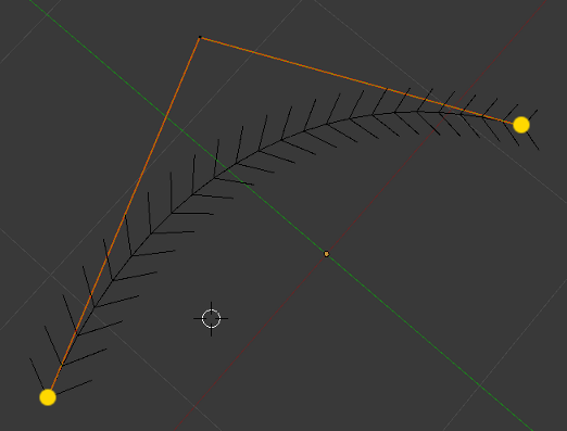
The reason why I (a few posts back) noted that a Path is actually an (open) uniform quadratic B-Spline*, is perhaps now a little easier to understand. A quadratic Bézier curve needs 3 control points. The control polygon (orange lines) is just the straight lines between these points. At both ends (yellow dots), a Bézier curve is tangent to its control polygon. You can see this if you take a Path consisting of 2 segments (which then is a quadratic Bézier curve):
* Edit:This is only the case if the order is set to 3 (and thus the degree is 2, quadratic). For me this was the default setting.
If you add some segments, the curve will be tangent at the center of a segment of the control polygon (yellow dots). This is typically the behaviour of a uniform quadratic B-spline. Note that at both ends, the curve is still tangent to the control polygon (orange lines):
So between each two yellow dots, the curve is just a quadratic Bézier curve! So in the picture above, the quadratic B-spline consists of 4 quadratic Bézier curves (there are 4 segments). If you would separate them, it would look like this (easer to recognise the 4 Bézier curves):
Hope this makes my explanation a little easier to follow!
[Edit]
So to conclude, when you would project this B-Spline in the picture (3D) above to a lower dimension (so from 3D to 2D), this projection would be a NURBS, a piecewise rational Bézier curve. This is true because each segment of the B-Spline is an ordinary Bézier curve, which gets projected and results in a rational one).
i know that you can use a 3D curve instead of a path curve
but may be path are simpler only one control point and be like a parabola instead of a cubic equation!
i tested in bmesh with error !
i think you should ask for a version working with Bmesh
cause most of the next SVN will be with Bmesh so if you want it to work later on
it should work with Bmesh i think!