I´m currently trying to create an animation-loop of lasers for an industrial animation. The basic idea is that I input any curve and the laser shots from an origin point towards the start point of the curve, moves along the curve and retracts when reaching the end point of the curve. In order to dynamically change the speed of the process I used this simulation nodes tutorial from harry blends https://www.youtube.com/watch?v=kiY5R4bzA4U to create 4 separate stages. They don´t have any crazy conditions like in the video, but just different frame lengths, the phases should work like this
- Phase 1: The laser is fully contracted and new item is moved into place by a conveyor like loop
- Phase 2: The laser extends to the start point of the curve
- Phase 3: The laser follows the curve till the end point
- Phase 4: The laser retracts from the end point of th curve
Right now I’ve suceeded in creating a setup that retracts and extends when needed
and one that follows the curve as needed.
Both of those are achieved via the set position node. I tried to bring both effects together, but ran into several problems. Just using two separate set position nodes in series doesn´t work. Thus I tried instead to make use of them trim curve node to reduce the length of the curve. This works to an extent, but only with fixed values
As soon as I link a noodle with a field value the trim curves node doesn’t work anymore. Do you have any idea why? How could this be prevented? Or do you have any idea how to achieve the described animation with a different method?
i would recommend providing a blend file. Why? you want help for free from us in our spare time, right? so you should make it as easy as possible for us to help you. I would help you if there was a blend file provided - but for sure i don’t want to rebuild this all manually just to explain you how it could work.
You are certainly right, I was not sure if it is best practice around here to drop your files on the first comment. But thanks for pointing that out.
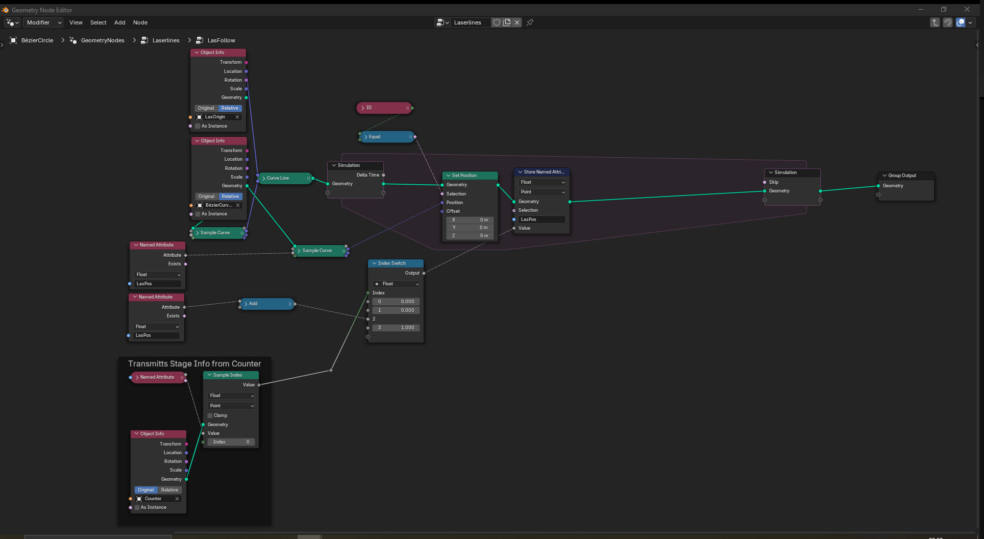
Laserlines.blend (825.9 KB)
Your simulation zone is not needed as it does nothing.
The point of the simulation zone is that it is a place where you update a value each frame depending on what that value was the previous frame.
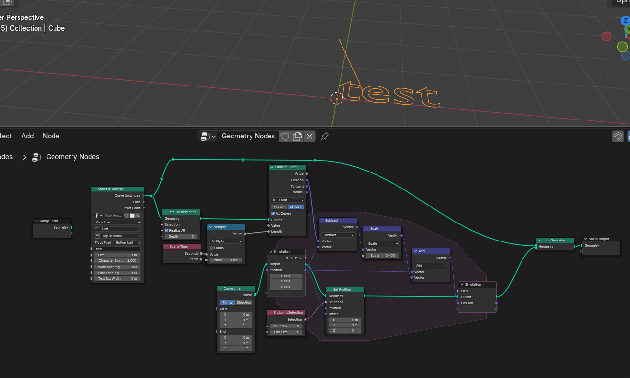
E.g:
Here the curve is being swept by the frame time while in the sim zone the position “lags” behind. The animation is controlled by changing the multiply and the scale factors.
Good luck.
Could you please elaborate what you mean by “it does nothing”, I´m pretty new to simulation nodes. Isn´t the zone doing something as the curves are moving and looping the animation with certain frame ranges?
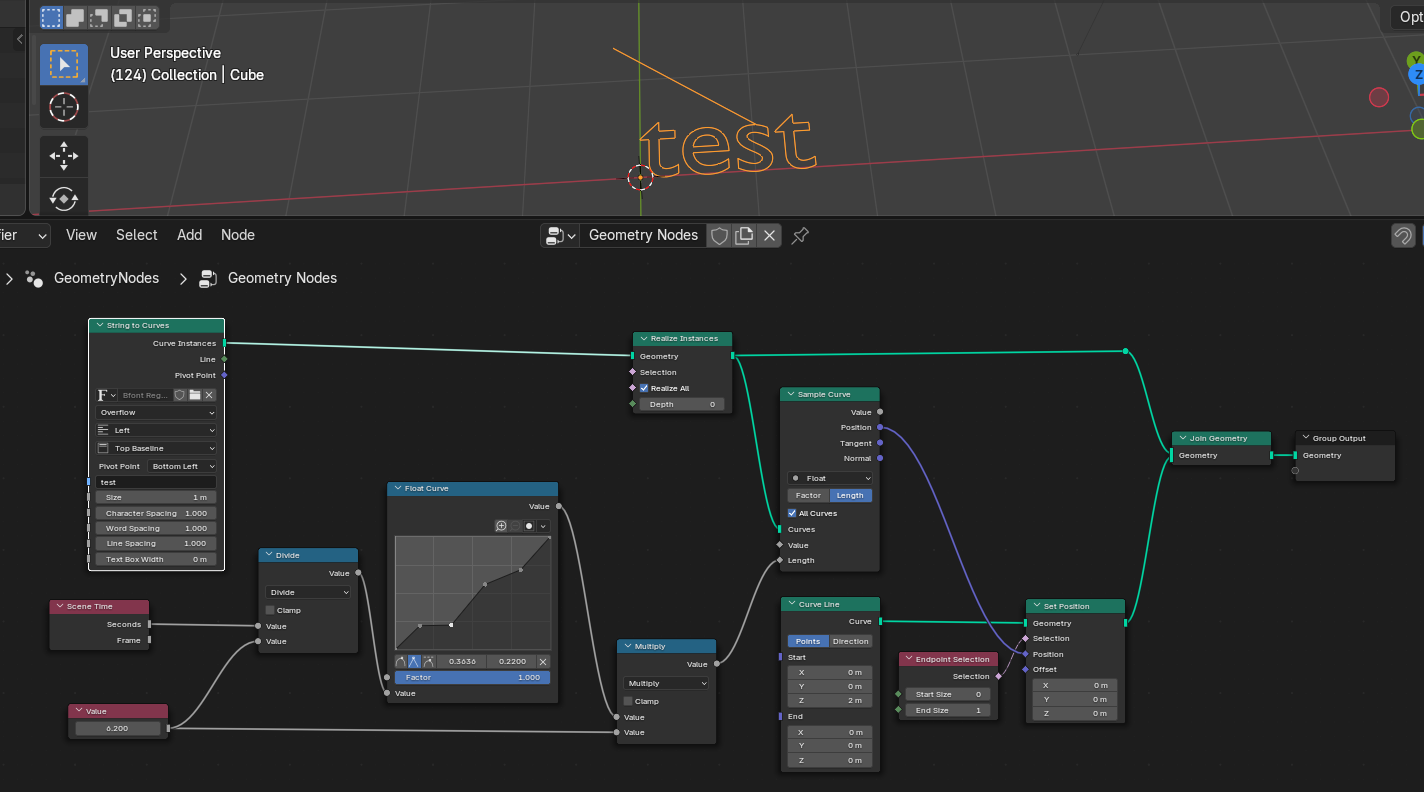
Sorry, yes, you are using named attributes so it does do something…
I meant that there is no dynamics. You may as well use a Float Curve:
…here doing a 6 second animation with varying speeds. So better way of saying may be that the simulation zones aren’t necessary in your case.
In my example from the previous post, the simulation variables are using the simulation zone’s attribute plugs to ensure the feedback is explicit… Also, experiment with multiple sim zones if you have you.
The other issue I noticed is that you are not doing like-for-like in your trim and sample curve
…disconnect the cyclic splines and work off of everything joined so the trim acts like a “All curves”… i.e. force one curve and then length is length for sample and trim.
Good luck.