Hi,
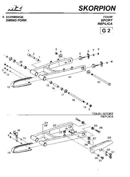
I have a parts book that contains exploded drawings of the parts in my motorcycle. Is it possible to import a scanned image of a drawing into Blender and create a 3d version of each part by tracing? The parts in the drawings are all in perspective view, so I don’t know if this makes it more difficult? Tutorials I’ve seen up to now have all used drawings that use front,side and plan views.
Can anyone point me to a tutorial (motorcycle specific if possible) or give me some ideas I can pursue?
Thanks.
David.
P.S I’m new to blender and modelling but would like to use a real project like this to learn more about blender.
yes if you can scan a complicated part then i guess it is worth to scan and import picture as background in blender then you can draw it with some tools in blender
don’t forget to use mirror if there are any axis of symetry in model
that will save you time!
also if part are rounded then you could use the subsurf
but show us the part you have scaned and then begin and show pic here and ask questions about specific things for the model your doing
now for simpler parts it is probably easier to draw it directly in blender no scan needed here
I don’t think you would benefit much from using that image as a background in blender. If I were to model those objects, I’d simply use the image as a reference (as in I’d look at it every once in a while) and try to get the proportions right. The object is fairly simple, so you shouldn’t have too much problems with it
Would it be easier to model the whole motorcycle from photographs to begin with? I can take photo’s of the front,rear and side but not from the top (as I can’t fly). I think this would be more realistic and achievable than modelling each part.
Anyone know of any software (free) that can help me or any tutorials for cars that I can take some hints from?
Thanks.
for background images nornally you use a picture for the front side or top
the isometric view can be use to help you do the drawing but not as a background image!
now you first dwg it shows relatively simple objects so just begin to add objects in blender to reproduce theses objects!
like add circle then extrude to give some thickness and exterude for the lenght
now did you began reading about the intro to blender on how to add and edit objects in blender in wiki pages?
if not may be this should be your first task to learn some of the blender’s basic tools
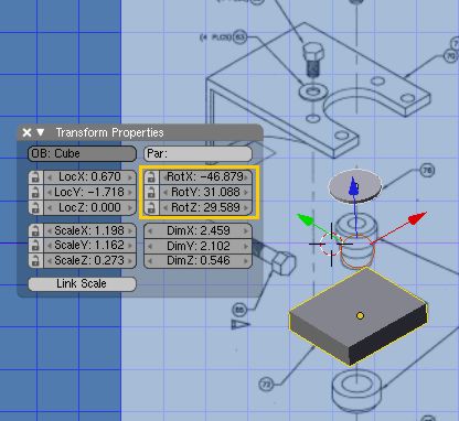
Proper Isometric drawing is done to scale. So the trick is to set the object coordinate system inline with the Isometric. And work from a view with background showing. So that when you extrude or translate it does it over the image. There must be a way to do that.
Here is quick experiment. Display background image than try to fit, rotate basic cub to one of the main element on the iso drawing. Once good fit is made Rotational information will be available in Transform Properties. Now other form can be made to that rotation. New object can be just duplicated from the first basic sets.
It will be easier if coordinate system can be set to that first cube. So that every item created from then on will be in that coordinate system. Scale, rotate action follows the new coordinate system. How do you do that?
to set the coordinate system to match the one of the cube, simply rotate the object in object mode and use local coordinates while editing (For example, to move something along the local x-axis press ‘g’ -> ‘xx’ instead of ‘g’ -> ‘x’)