trying to make some aniso metal of this type here
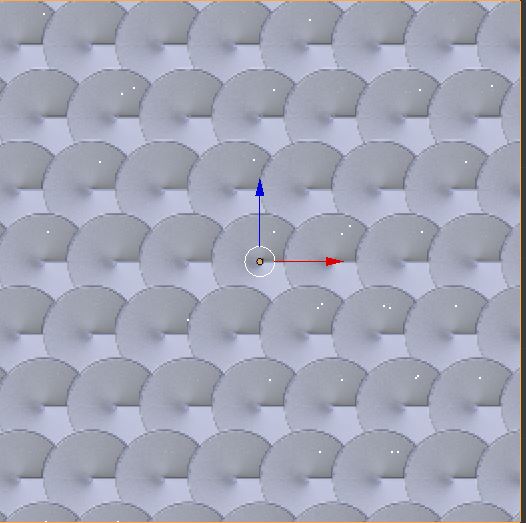
anyone has a nodes set up in cycles with some link for the maps ?
thanks
happy bl
trying to make some aniso metal of this type here
anyone has a nodes set up in cycles with some link for the maps ?
thanks
happy bl
here is the mat i’m trying to reproduce
sort of metallic shinning for a dashboard
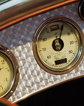
thanks
happy cl
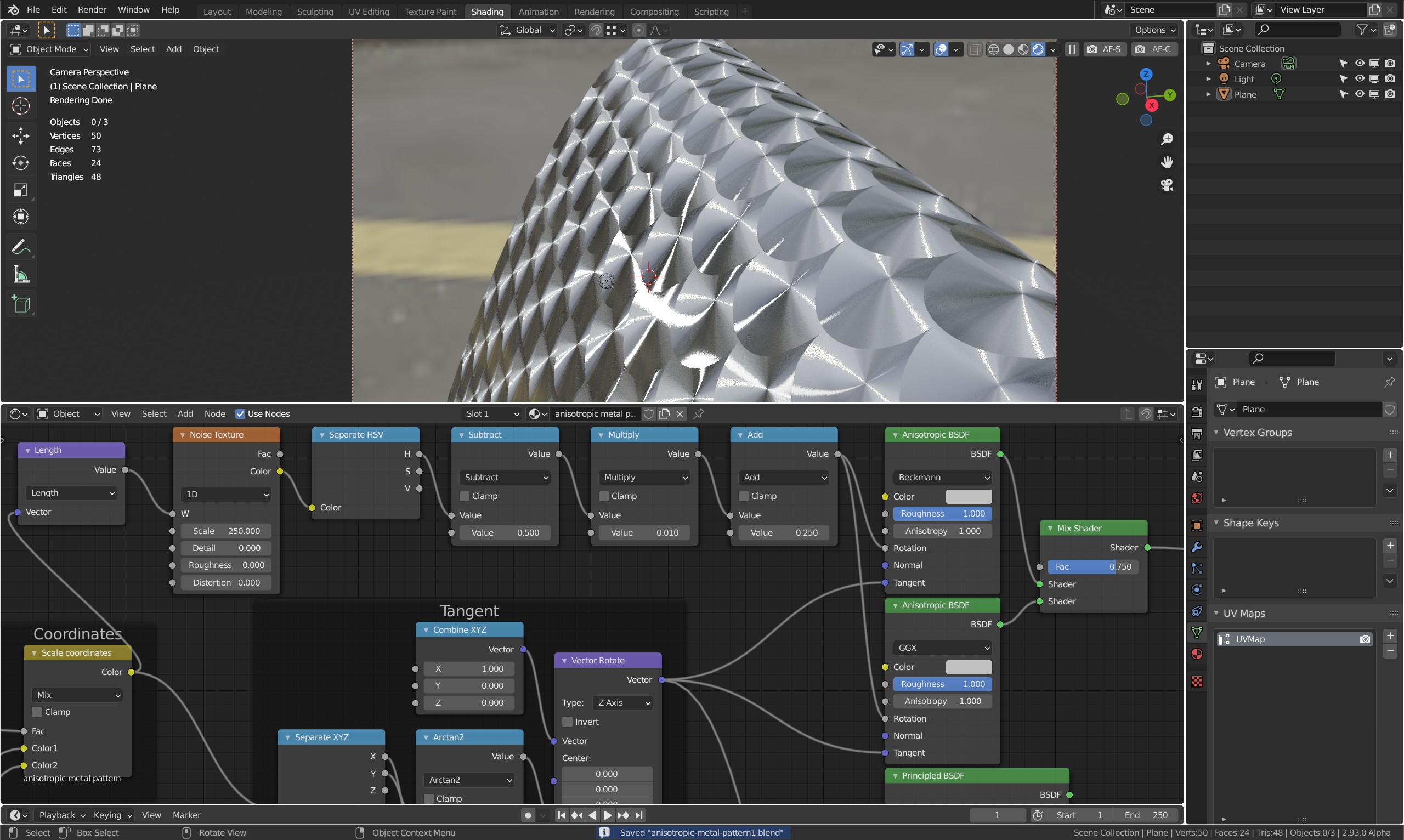
I made a similar pattern a while ago, while experimenting with scales. I adjusted it to drive the tangent for the anisotropic reflection:
Right now it’s basically only the procedural coordinates and the tangents, but it might be a starting point for what you’re looking for:
anisotropic-metal-pattern.blend (1.0 MB)
good beginning
i found a very old pattern a bit like the photo
but hard to get it to look like the shiny dashboard as shown in photo
can you explain a little how this is working
i see PBR node and with lot of roughness
when i turn it in front view
pattern seems to disappear is this normal ?
if i lower roughness on PBR pattern also seem to disappear
this pattern on a dashboard would be almost vertical so pattern has to be there in any rotation
another thing when you look at the photo of the dashboard i uploaded it looks a lot shiny or glossy
so is there some way to make your pattern nodes look more glossy ?
does this effect works with any type of light sources ?
or need some special set up ?
thanks for feedback
happy bl
I tend to use a mix of two aniso shaders; one ggx rough 1 shader and one beckman rough >1.5 shader - both with 1 in aniso, then mix them together. When using only ggx you have to drive the roughness up massively to get good light stretching, so you eliminate any sharper reflections - in my observed reality bright lightsources “stretches more” than weak reflections. And yes, obviously you need light sources and/or environment - preferably both for tweaking the mixing ratio.
In addition I find it useful to visualize the groove direction, in this case I’d just noise up the length of the finished coordinates → 1D noise → separate H → subtract 0.5; now you have -0.5 - +0.5, so you now just multiply with how much each groove should be shifted, and then add 0.25 (or not; if you have to add 0.25 for principled, you shouldn’t add it for aniso shader and vice versa - I’m not sure why these are still offset 90 degrees).
Looks like this, but I didn’t check if I need rotation or not (muted or active node - the stretching should be perpendicular to the groove direction):
thanks for tip i will built a new model and test that
happy cl
wow this node is too useful… thanks…
trying to rebuilt the nodes set up
can you show a bit more of the nodes set up
how is this image sent to the node on left
and also on the right to the output
and bottom part too
that vector rotate !
is this only in 2.9 or also in 2.79 ?
thanks
happy cl
Actually it’s a bit cheatish, as I didn’t modify anything to give me a random offset, so all grooves have the exact same randomness to them. They’re also circular, they don’t actually change along the groove. This was just to help visualize the groove so as to orient the rotation correctly.
@Ricky, you need later versions for the vector rotate node. But you can setup a similar rotate Z group node using simple trig.
but if add a ring wave texture can be possible to get out the right effect?
this is done in later 2.9 version i guess
and rotate node is not in 2.9
also is this using an image or a procedural texture ?
darn i got to wait till i can get a new PC
soon i hope
i will take a note for this aniso set up and be back later on when i update my PC
don’t know when !
thanks
happy bl
I wasn’t able to, it only made a weird wobble and the same wobble for each scale. I haven’t tested it on Erindale’s scale setup, but he tends to make stuff that use “per tile” randomness. A disk coordinate system would be better per tile (x=length, y=radial, z=random?).
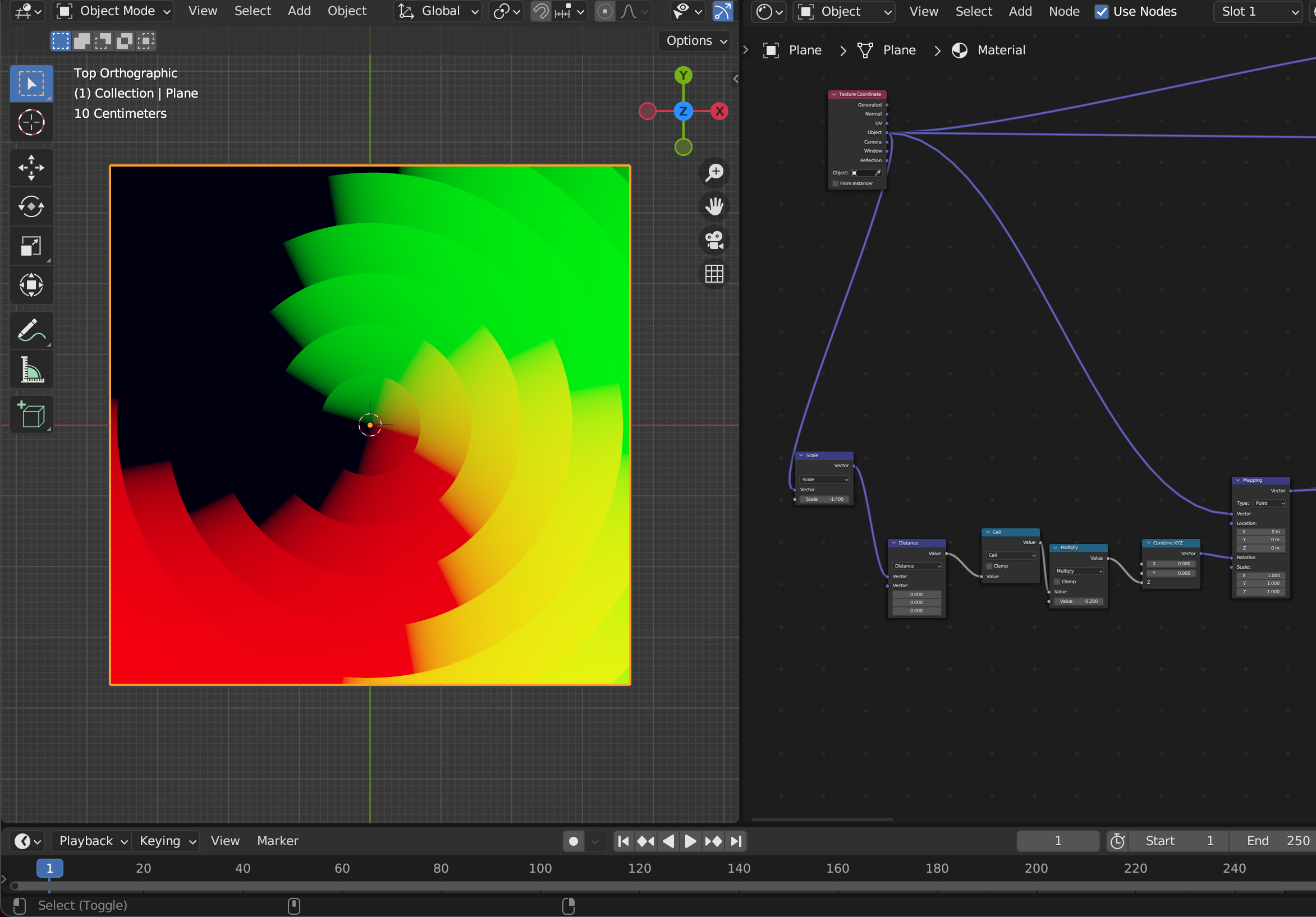
@Ricky: There is no image or procedural texture involved. The setup just creates the tangents needed for anisotropic shading. In the top image, you see that only tangents are plugged in, and everything in front of it is creating those tangents. It should be possible to create the same result using basic UV as tangent and per scale creating a half a radial that is used for rotation instead. It takes one coordinate system (UV) and transforms it into another coordinate system. Preview the x and y outputs for each set to see what’s going on.
Maybe with this node we can achieve the ring effect, I’m going to try it this week.
very hard to do without distortion.
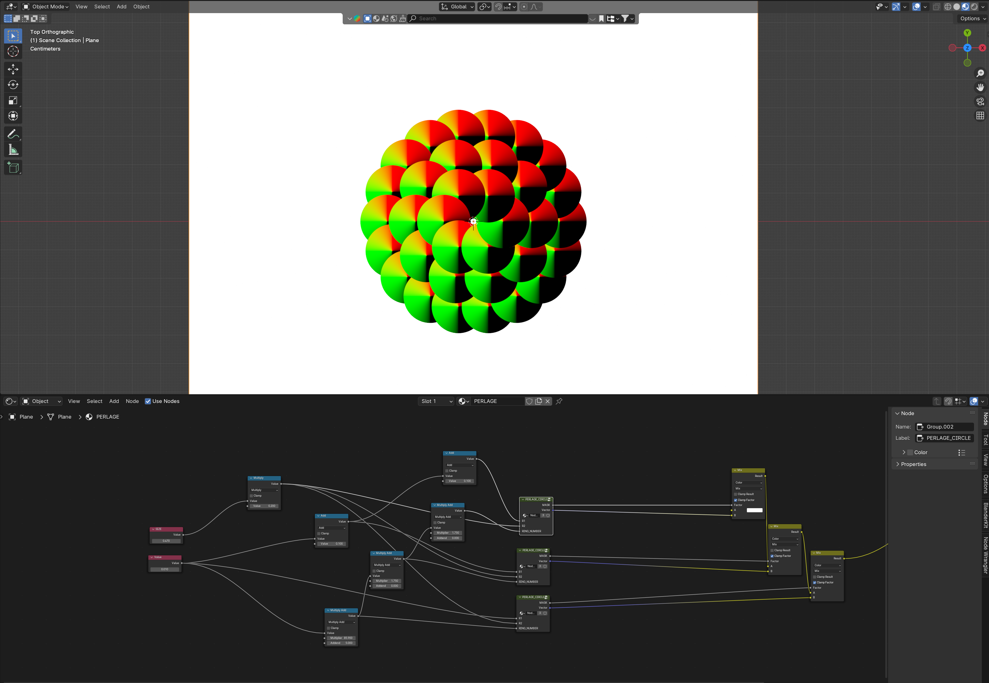
Edit : I don’t know if it the best solution but I did this with the help of this post
PERLAGE.blend (1.1 MB)