@Bruno there will be an update to the Blender task (https://developer.blender.org/T92571)
int the next two days, including some examples in complex and real-world rendering tasks.
7 Likes
i have tryed it,but i get this error.
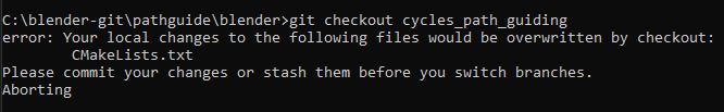
to me it makes sence that the cmake list is another then with the branch.
what to do?
I have added the entry manual in cmake since it was not listed.After making the build its path guiding GUI is not showing.
I think i still need another command line to load the path guiding branch.Then i guess would be the option WITH_CYCLES_PATH_GUIDING showing in cmake too,and not need to added manual !?
Any further ideas how to load a branch from git with command line?
Path guiding can help with difficult light paths - caustics are one example, but not the only one.
In theory - it should lead to cleaner/less noisy renders given similar number of samples - especially in scenes that have difficult light paths.
I am no really a git expert in any way.
Do you have change something in the source code?
git reset --hard
undo this changes.
Make sure you are in master: git checkout master
I guess this is off topic for this thread, may you open a thread in Coding or:
Cheers, mib
1 Like
Guys, what do you think, will “PG” be useful in interior scenes?
I’ve got few questions about path guiding:
- Will be there need for using light portals for closed spaces (interiors)? (setting up rectangle lights with “portal” checkbox is quite tedious)
- Can it produce better caustics without MNEE? Or it would be better to check both techniques?
- Will it produce reflection caustics?
I’ve been following the weekly updates of @lukasstockner97 about the Principled v2. He also wrote up a pretty extensive design doc about it.
I don’t get all the technicalities. Could someone more knowledgeable enlighten me ? I understand that this is about simplifying the model, but should we expect performance and/or quality improvments ?
Anyway, an update is exciting !
1 Like
I can’t say I understand all he wrote, but from what I could gather, this is a big change.
First of all, better fresnel for metal. (quality boost)
Then, Subsurface Color will be gone (use base color instead), and the Subsurface slider will be replaced by a Scale slider.
- Subsurface color is unnecessary
The thing is that the current Subsurface slider is doing two things: 1. mix the base color and subsurface color 2. act as a strength scale for SSS. This feels strange if you think about it. With Subsurface Color gone, you no longer need to consider which color it would produce when it mixes your orange base color with cyan subsurface color, when changing the SSS strength the mix factor would also change etc., it will be just controlled by the base color, and scale is just scale. So much simpler.
Subsurface radius (RGB vector), scale (0-inf)
Another nice thing about removing the mixing of base and SSS color is that the scale no longer needs to be 0 to 1, it is 0 to infinity. Previously it also acts as a mix factor so you cannot go beyond 1, now it can.
- IOR (0.1-10 or so)
Affects dielectric specular, refraction and subsurface
It seems we no longer need to have Subsurface IOR as separate from IOR, they are now the same slider.
- Sheen strength (0-1), tint (RGB), roughness (0-1)
- Clearcoat stength (0-1), tint (RGB), roughness (0-1)
These two tints will be RGB color input instead of the current arbitrary float slider values.
- MultiGGX is a headache - slower, noisier, has bugs, hard to maintain
- Replaced Multi-scattering GGX with a albedo-scaling factor on top of the regular GGX closures
Multi-scattering GGX will be gone, and regular GGX will be modified to have energy conservation to replace it. (performance and quality boost)
etc…
It seems a big big change.
My interpretations above might be wrong, these are just my understanding.
11 Likes
Awsome, between that and path guiding, sounds like Christmas will arrive early
Current Subsurface Scattering settings are more ancient than ability for vector sockets to handle color textures.
Nowadays, user can plug a texture to control SSS directly in SSS scale.
So, other SSS settings are obsolete.
Using one IOR setting should result in materials more coherent to physical expectations of a uniform matter. To create heterogeneity, you will have to use a mathematical formula or a texture or blending of shaders, instead of different values for different sliders.
For that part, total newbies (who were moving the sliders without understanding) should produce less non-sense materials.
But intermediate users will be forced to become more technical.
So, quality of materials should be improved. But there will be a phase when users will have to relearn how to obtain expected material with principled shader.
Model should be more respectful of energy conservation. But that does not mean that performance will be improved for all use cases. SSS refactor could have as a downside an higher cost on render time.
The thin surface mode will be a way to skip heavy volume computations. That should be a performance boost for thin surfaces without perceivable quality lost, but compared to thick mode, not to previous principled model.
There will be less settings. Compiling of shaders would probably be simpler and faster. But on the other hand, a more physically correct shader will take into account things, that user could have neglected : that would lead to more computations.
So, don’t expect performance improvements. That could be the case for some uses.
For some uses, there could be regressions.
We will discover that, when shader will be available for testing.
6 Likes
In the design doc it is said to be:
I guess it will be a check box to turn on or off, and it’s about a non-refractive transmission, I imagine use cases being window glasses etc.
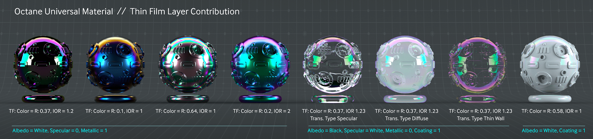
The typical example is that iridescent look of soap bubbles, or oil on rain pools…
It’s a micrometric-scale layer, that gives subtle optical effects. An practical use case, added to the above ones, is the specular color shifting of treated materials like leather (think of black leather in car interiors).
It’s funny that you, @thinsoldier, ask about thinsurfaces… ![]()
4 Likes
I think that is not thin surfaces, but “Iridescent coating” (also mentioned in the design document linked above). See the linked example: https://belcour.github.io/blog/research/publication/2017/05/01/brdf-thin-film.html
It is what, for example, on Octane is called “thin film”, and hence the confusion!
As @Eary_Chow wrote above, I think the thin surface checkbox Lukas Stockner is implementing will be useful for windows. I imagine it will allow, for example, archviz people to finally stop using the “glass hack” shader to reduce noise in renders.
I guess this is for leafs rendering.If you remember all the translucent node tricks etc.to get the light appearence of the leafs right.
1 Like
“Thin surfaces” here means a mode that simulates two surface interactions at once.
For example, imagine you want a sheet of frosted glass - usually, you’d model that by taking a cube and scaling it down to ~cm or so on one axis. Instead, with thin surface support, you can just take a plane, activate that checkbox in the shader, and it will shade it as if the light path hit one side of it and then immediately the other side.
In particular, that means that instead of “real” refraction, the rays coming out on the other side will not actually be refracted (because, in the real geometry, they would get refracted into the model and then immediately be refracted again going out, leaving the angle unchanged).
Cases where this might be interesting are e.g. thin glass, leaves, paper etc.
For details, see slide 53-61 in https://blog.selfshadow.com/publications/s2017-shading-course/imageworks/s2017_pbs_imageworks_slides_v2.pdf.
Additional things that could be added to it are e.g. translucency and automating the “architectural glass” ray visibility trick when roughness is zero.
25 Likes
That’s not what it means here. No diffractive effects are gonna be added. It’s just a technical thing:
Normally, the IOR on the back side of a surface ( where backfacing returns 1) is 1/IOR on the front
This is fine if your mesh has volume. It represents going from the optically dense medium to the optically less dense one to correctly model total reflection and such.
But if you have an unclosed surface, such as a single planar face as a window, you gotta pretend that both sides are “outside”, so you actually need to undo this inversion, inverting again if it’s backfacing.
It’s a simple setup but not very discoverable, so to have it be a simple check box is gonna be great
Btw, if you’re like modeling the surface of the ocean or something, you don’t need the thin film change: this is only for if both sides of the material are “outside”/air. But here one side is gonna be water so the fresnel output wo already be correct (if the surface normals point outward into the air/vacuum)
You can also, in principle, model a thin film separating two different media. Like if you have a bag full of water or something: outside IOR needs to be the plastic’s , inside needs to be plastic IOR/water IOR
As a somewhat related aside, one thing I really wish Cycles had is a solver for multiple intersecting media. Right now it’s really tricky to correctly model something as simple as a glass of water. You basically need to modify the IOR where glass and water touch to be glass/water but where there is air, you need it to be the regular glass IOR.
If you attempt to do this by having the water surface at the glass coincide exactly with the glass, you get coplanar surface shading artifacts.
If you instead leave a small air gap… Well, you got an air gap!
And finally, if your make the water just a tad wider, you get a really strange unphysical result.
There would have to be a way to go “ok I have these mesh volumes overlap, but really render it like they are in contact at the glass mesh, ignoring the bit of water inside the glass, and calculate the IOR accordingly”
Some renderers have such systems
EDIT:
Here is what the thin film checkbox would presumably do, except in this example I allow the inside and outside material to be different. A setup like this might be a (thin) piece of glass behind which you have water.
I’m guessing the tickbox will simply assume both sides to have the same material, i.e. air (or vacuum) with an IOR of 1
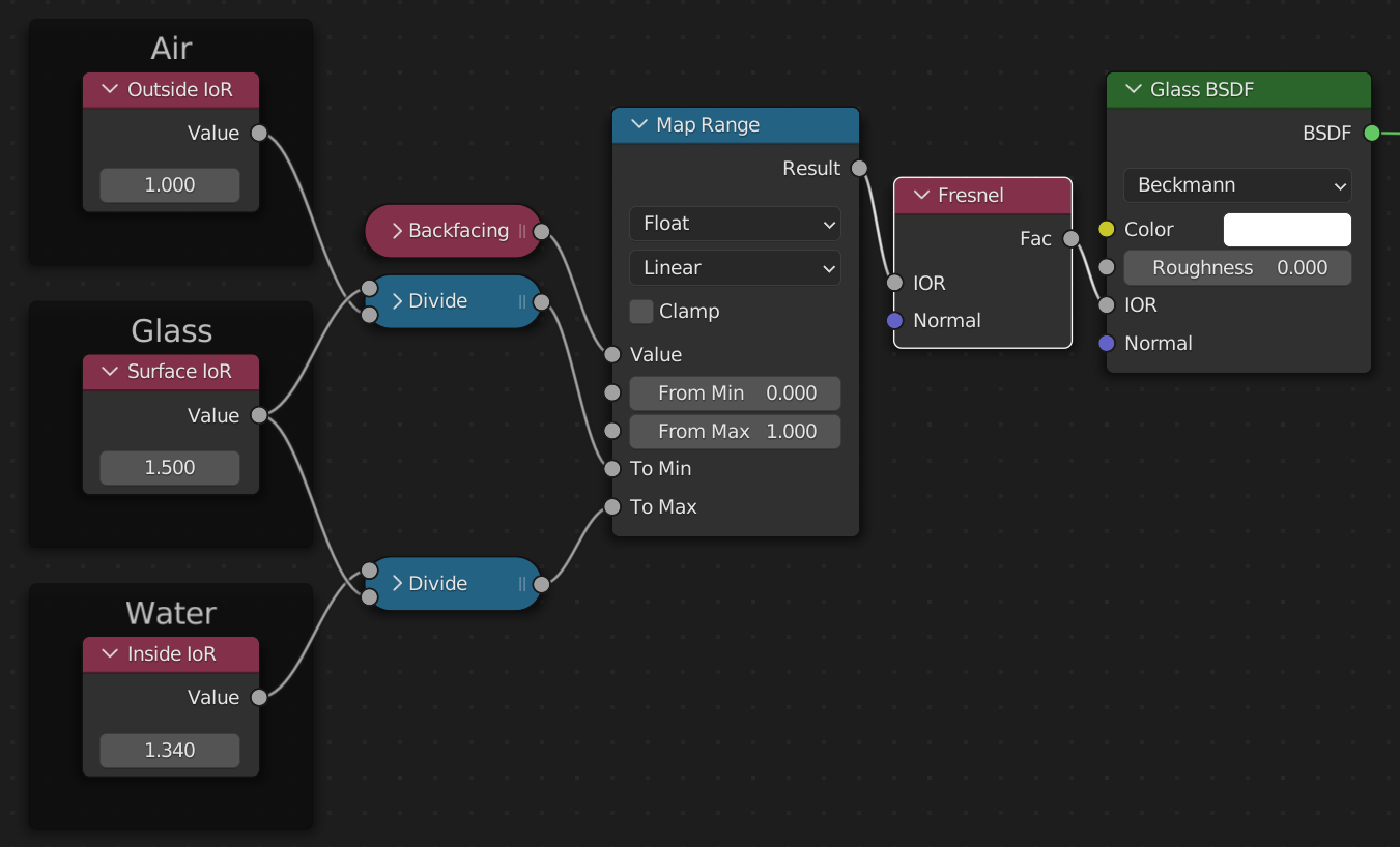
'course the full Principled shader will be much more complex and it will have to consider that surface IOR in many other locations.
You could, in principle, also add extra layers of thin materials on top with fancy chains of mix shaders and fresnel. That’s not actually gonna give you fancy thin film effects though, as you then would have to consider diffraction which this setup completely ignores.
But anyway, whenever you want just an infinitely thin sheet of some refractive material, you technically would have to do something like that to make it be “correct”