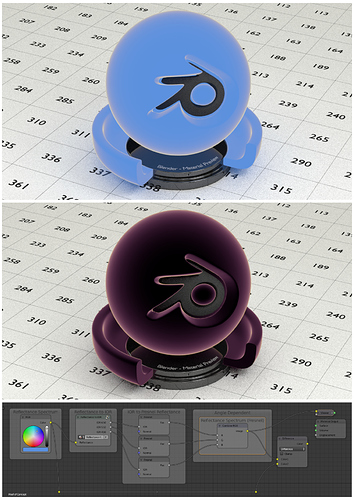
Here’s the proof of concept:
It’s missing the actual RGB to spectrum conversion and vice versa, but it seems you’ll know what to do with that. In the second image, the new angle dependent reflectance spectrum is compared to the original reflectance spectrum using a color difference node (I actually recommend you try using this node to better compare/illustrate your spectral vs RGB tests!). You can see how at normal incidence, there would be no difference. And of course, there would be a whole spectrum of resulting IOR values instead of 3.
Unfortunately, I realized there’s another problem with this as I was testing different spectrum inputs. Due to the asymptotic nature of the ‘reflectance to IOR’ equation I used, as reflectance approaches 1, the IOR values approach infinity. In those cases where reflectance at normal incidence is very high (maybe > 0.20), you’d probably be describing metals/conductors instead of dielectrics; you would want to find complex IORs instead (and by extension, use the complex Fresnel equations). Like I mentioned before, we can’t really solve for a complex IOR without more information.
In the example image, the IOR at the 450 wavelength would be calculated as ~12.7, a point at which it should probably be complex.
Anyway, here’s a .blend file: IOR Proof of Concept.blend (3.0 MB)
