I have a plane with a cycles material applied to it.
Now I want to add a noise texture as well. The distortion of the noise texture should get bigger from left to right.
E.g. at left side the distortion value should be 1.0 and at the right side it should be 2.0. Between 1.0 and 2.0 there should be a linear transition. I could not find any input value, which I could connect to the distortion input of the noise texture.
I need something like a gradient from black to white which is dependent on the planes edge coordinates.
So left edge should give a value of e.g. 0 and right edge should give value of 1. Using a math node I could translate it from 1.0 to 2.0.
But I cannot find any input value which gives me black and white transition dependent on planes size / edge position.
UV unwrap your plane and use UVs for input. Or even plain and simple Generated texture coordinates. Either shall give you a 2D vector in [0,1] range, which is easily converted to [1,2] by just adding 1 to it. Using Separate RGB node you can extract U and V values, gaining access to both “horizontal” and “vertical” directions.
thanks for reply, but this helped only partially.
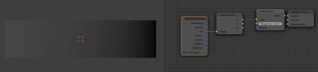
I have the node setup as shown in my image. If I plug the output of the ‘RGB to BW’ node into the input of the ‘Diffuse shader’ node I can see a linear transition from left to right from black to white. So far it is working. I tested this now with the brick texture and plugged the output of ‘RGB to BW’ node into the ‘scale’ value of the brick texture. As you can see the size does not only change from big to small it seems there is also a vertical component which is distorting my texture.
How can I make it that the bricks from left to right just get smaller without this vertical distortion?
thanks but your last answer, as you may understand, is not very helpful for me.
As you can see in the screenshot of my last post I already use the ‘Separate RGB’ node and it’s red-channel as input to the ‘RGB to BW’ node.
In following screenshot I put the red channel of ‘Separate RGB’ directly into the shader node. The output shows a linear blending from white to black. There is no vertical distortion or component visible.
But if I use this as the size input for brick texture I get this vertical distortion - but I cannot understand why?
I have only a horizontal blending but as input for size value I get also a vertical changing - where does this vertical part come from?
The vertical part comes from the bricks - you’re not scaling just ‘brick width’, but ‘row height’ as well, and both these scales change from left to right.
Sorry, mr.burns, my bad, never should’ve posted when tired. And yeah, as spaced already explained, the ‘Scale’ controls overall size of the bricks. In your case, the scale increased left to right, making all of the bricks on the left appear bigger than those on the right.
One additional observation: in your previous setup you used ‘RGB to BW’ node after ‘Separate RGB’: this is not needed, as you already get scalar value from ‘Separate RGB’.
@Stan: never mind at least you gave me the correct starting point! @spaced: Thanks a lot, this was exact what I was looking for!
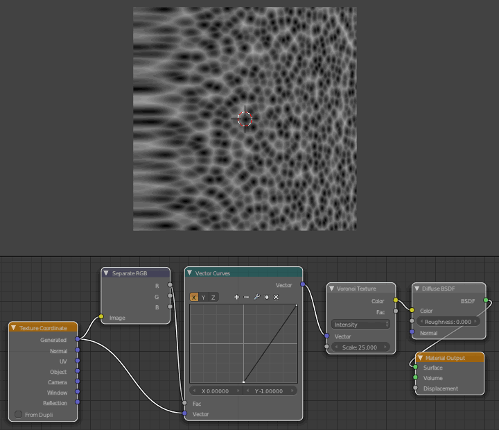
But I have a further question, what if the texture does not have a width and height option and I want to scale e.g. a voronoi texture only horizontally - is this also possible?
Procedural textures are generated from input coordinates. By scaling these coordinates you can effectively scale your texture. Filter your texture coordinates through Vector->Mapping node (plugging it’s output into texture’s Vector input) and then change X/Y scale in that Mapping node. Reducing scale will “enlarge” the texture while increasing the scale will shrink it.
Alternatively, you can use a combination of Separate RGB/Math/Combine RGB nodes or even Color->Mix RGB node (in Multiply mode) to multiply your coordinates (if you want to e.g. make scaling values accessible as inputs).
Can you post a picture/diagram of the resulting material effect you are trying to achieve? (Might be quicker than then working our way through Wave, Musgrave, Gradient, Magic, and Checker
thanks again that finally solved my problem. There is no special effect I want to achieve I just want to understand more in depth how the texures in blender and especially with cycles work.