I’ve had an idea for quite some time and have not been able to figure it out. I’m asking in the hopes that someone with a bit of python knowledge can help get this idea off the ground. It’s possible that I’ve overlooked a simpler method to solve this without the use of scripting.
I’d like to drive a shapekey value based on the weight map of a sphere.
I’m sure that others have had the same frustration as me when creating corrective shapekeys for bones that use quaternion rotations. I believe this solution will alleviate the math madness and give a solution that will be visual and predictable.
I’ve included a blend for use as a testing ground.
The goal will be to drive two shapekeys on the cube based on the vertex weights of the sphere. The vertex groups on the sphere are named to correspond with the shapekey they should drive.
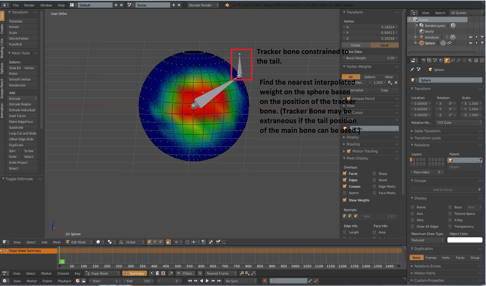
Rather then using transform channels locations or rotations in a driver, I want to drive a shapekey by using a weight map. To do that, I need a solution to find the position of the bone’s tail, find the nearest vertex on the sphere to that location, then find the weight of that vertex in a specified vertex group.
That would take all of the fun out of this wouldn’t it? Besides, weight painting is my favorite task and I’d hate to give up more chances to pull my hair out.
My two cents…
Start flat. Figure out how to extract your weights using simple X,Y coordinates. Using a UV sphere you’re actually just referencing a 2D grid anyhow, wrapping it to a sphere just adds a layer of complexity that, as I see it, doesn’t add any major benefits.
Maybe my mind is simpler then you give me credit for. The benefit that I see is a perfect visualization of the bones rotation towards a point on a sphere and the value of the weight at that specific point.
I’m not sure I could imagine the rotations of a thigh onto a 2d grid… A typical person can rotate their leg 55 degrees backwards, 120 degrees forwards (unassisted), and 45 degrees to the side with your feet facing straight forward. (Splits are only possible if you rotate your feet outward.) That represents more of a sphere to me. By posing the armature and having that direct visual feedback, I think it would be trivial to set a weight on the sphere to the value wanted in the corrective shape.
One thing that must be considered is the sphere must scale with the bones length so it’s radius remains consistent. I have that figure out with a copy location and a transformation constraint that remaps the Y scale of the bone to the x,y,and Z scale of the sphere.
It’s possible that most of the scripting functions to make this work have already been written for the weight transfer tools. I’ve been working on finding those.
Okay, that is a major benefit. If it’s driving corrective shapes for a joint, having a sphere makes assigning (painting) the weights much more intuitive. Point taken.
Sorry to necro, but did we ever figure this out? I’m attempting to do the exact same thing right now—that is, tie a driver to a vertex weight, in an attempt to use it within a material.
I’m going to try a few more tricks for my own edification before I default to something more readily workable.
For the OP, as described, this is certainly possible.
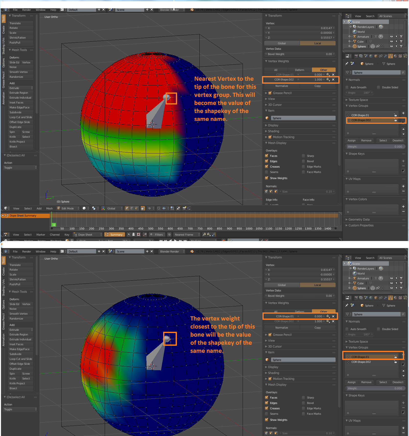
We want a value representing the nearest weight from a sphere to the tail of a bone. So we make a non-rendering, zero-area face at the location of the bone’s tail, bone parent it to the bone, and then give it a data transfer modifier targeting the sphere, on nearest face interpolated, copying weights.
That zero area face now has the particular weights we need (on all four verts). How do we measure what those weights actually are? We can use any number of different deform modifiers to do this. Let’s use a warp. We’ll give our zero area face a warp modifier, after the data transfer, limited by the copied vertex group, with no falloff; then we’ll set up two empties, one at world 0,0,0 and one at world 0,0,1, and we’ll set those as to the to and from targets for the warp modifier.
Now, our zero area face moves up a number of world space units equal to the nearest weight. How do we get this deformation into a driver? Again, any number of ways. We’ll do it by editing the armature to which its parented. Create two new bones at the location of our tail, and parent them to the bone. Make sure they are not “connected”. Give one a shrinkwrap constraint targeting our zero-area mesh. The distance between these two bones is equal to the weight (nearest face interpolated) of the sphere. You can use distances just fine in drivers, so this should be as far as OP was asking to go.