Hi, so I’ve been learning geometry nodes and making projects around it for the past year, and I got into a problem with aligning instances. I searched the solution and fixed it. However, I am unable to understand what the nodes do. Specifically, fixing the problem is connecting 2 nodes, “curve to points” being the output and “align Euler to vector” being the input. I don’t understand what connecting rotation to rotation does and connecting normal to vector does.
Thank you in advance.
Have you looked at the Curve to Points node manual page, the Align Euler to Vector node manual page and Euler term glossary entry?
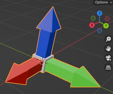
Have you made one of these and used that as your instance object to try understand what is going on?
Have you played with the Factor slider on the Align to Euler node?
Have you compared aligning the X to the normal followed by the Z to the tangent and then compared that to the Curve to Point’s Rotation output?
It is difficult to guess what exactly it is that you are not understanding. Maybe show the portion of your network that you are struggling with.
Good luck.
3 Likes
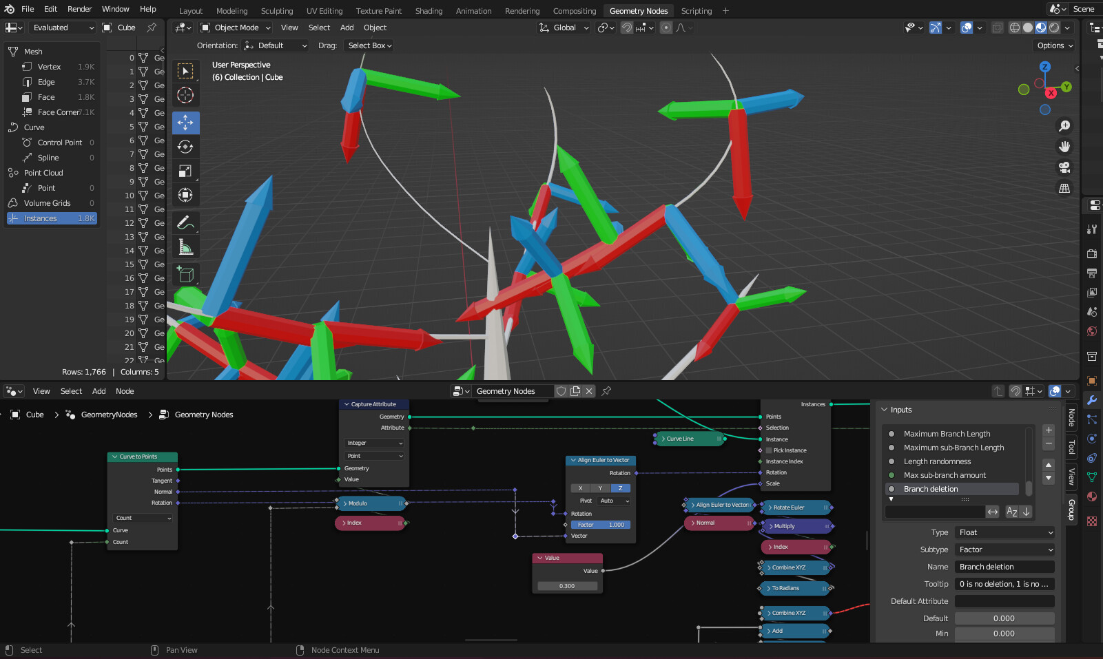
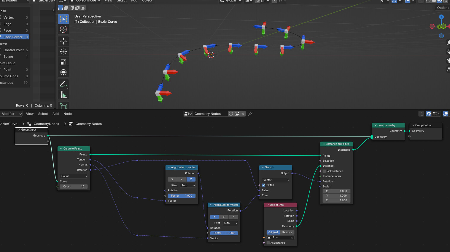
Here are all of the important nodes and their variations. What I don’t understand is what the rotation connections do and their relation to the normal connection. I do understand what the normal is and why the x axis is tangent to the curve, but not how it is affected by the rotation connection.
The align euler to vector node takes a rotation (euler) as input, and a vector.
The result is a rotation (euler) that way you can chain rotation if you like.
Or in some case you can leave the rotation socket empty so the euler input value is 0,0,0 …
Does that makes more sense ?
1 Like
no, not rly, i dont understand what the rotation from the curve to points actually output
IIRC, it’s a rotation formed by the tangent and normal.
If you do a cross product of the tangent and normal you get a third axis and I’m pretty sure the rotation output align to that.
The rotation socket avoid adding the extra nodes to get that rotation from tangent and normal, but it’s more a handy shortcut than anything.
Anyway, it’s been a while that I didn’t look into that so I might forget something important.
1 Like
so by inputting both the rotation and the normal nodes, the rotation (which we will simplify to normal x tangent) will have the normal part removed leaving the tangent rotation?
Normal and tangent are vectors, Rotation is a Euler rotation …
Doing normal x tangent will give you a third vector, and these 3 vectors altogether can be translated into a 3D rotation.
If you plug the rotation output right into the instance on point node’s rotation socket. That RGB axis model should align to the Normal , Tangent and Normal x Tangent axis of the the curve to point node.
I lack math knowledge to give you a more precise answer you might probably look for.
1 Like