Hello, everyone!
I am looking for some advice. I started a project modeling a very accurate (as accurate as I can make it) animated model of an F-14D Tomcat jet. I just finished a tutorial by Chris Kuhn on rigging the flight controllers of a jet, and wanted to apply that to something new. After doing some research, it seems that the landing gear of a tomcat not only contracts, but also rotates. I have attached a movie clip, which is not mine, of a basic animation of the behavior. I have also included a render of my strut so far. I am not quite sure how to approach this, since the strut has several linked pieces. Do I just use constraints, or would using bones be most effective? Or perhaps a method I am unaware of? Any help is appreciated!
I haven’t been able to attach the movie clip, but here is a dropbox link.
Hmmm, complicated! Assuming there’s a slight offset to let everything fold up like that.
I’ve had a go at doing it with bones, although I suspect rigid body constraints might work as well. This has one main control to fold the gear up and down, all the rest of the twisting and bending is dealt with using an IK constraint and a locked track to line everything up.
Hopefully someone else has other suggestions, there may be a more elegant solution out there…
Thanks, Bender007! I am kind of new to all of this, and I may have bitten off more than I can chew, but I am determined to try and figure it out. If nothing else, it is a good exercise in constraints, bones and IK!
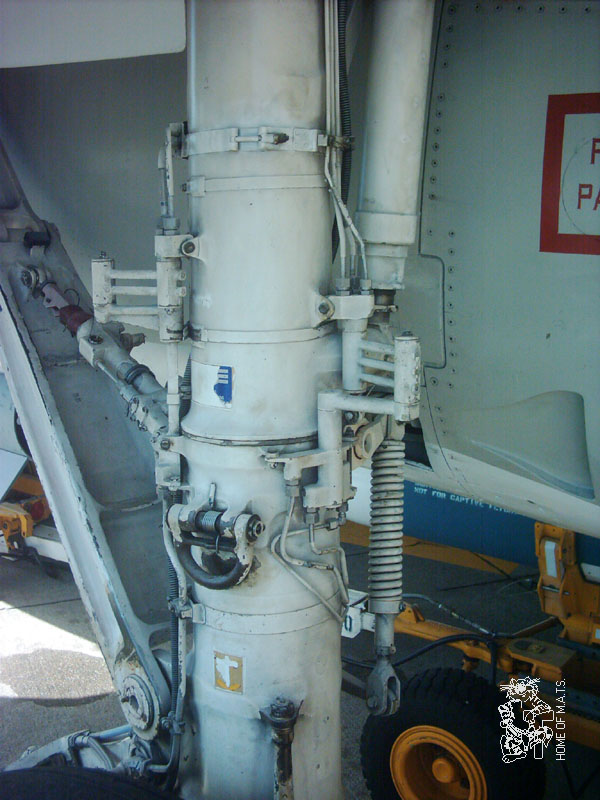
It shows the u/c retracting forwards, not sideways as you have it, sorry, but your rig would destroy the engine! There are lots of photos on that page that will help you and not a ball and socket joint in sight! The bottom section of the main strut rotates to allow the wheel to lie flat in the leading section of the wing, this is shown on one of the photos. It would still be good to get some drawings - you could always ask the MIG or Sukhoi factories - they are bound to have them! It also seems that the bracing struts are there to stop the main strut rotating backwards on landing, so I would contend that they must be straight and are pushed out of line by the small cylinder attached to the main strut one end and the lower bracing strut the other as below:
The red bit has a “remove before flight” flag on it as shown in one of the other photos on the page referenced above. The main deployment cylinder is behind the main strut, again shown on one of the photos. This photo above also shows the way they get the hydraulic pipes to move around a rotating part - the bits that stick out with pipes going into them top and bottom.
Thanks, Clockmender! My plan is to try to model a high resolution model of the F-14 with all the moveable parts animated. Wings, stabilators, tail, engine nozzles, canopy, etc. I even want to animate the anti-collision lights and all. Chris Kuhn’s tutorial was what inspired me, and I thought a big project like this would serve as a way to apply these processes and concepts to my own project. I went out and bought a plastic model of the F-14D super Tomcat to serve as a guide to modeling.
If you have any other suggestions or advice, it will be greatly appreciated!. I am checking out that other thread you had linked to as well.
You’re welcome, I have had a quick look at the mechanism, it’s actually the bracing struts that rotate the bottom section as it retracts, the top “hinge” of the top strut is able to rotate in two axes, which imparts rotation on the lower half of the main strut. If you like I will make a quick mock-up over the next few days (once I have done everything on Mrs. Clockmender list) so you can get the basic principle. You can then think about applying that to your model once you have the basic bits in place.
Keep up the good work - this looks like a nice project - you should post it to the Work In Progress section of this site.