Cool! The “solution” I had clipped the values. Awesome. So I will have to make another clip to rectify my mistake. Thanks!
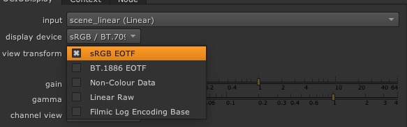
Hummmm… I don’t have the same options as you do. This is what I have:
It is a match.
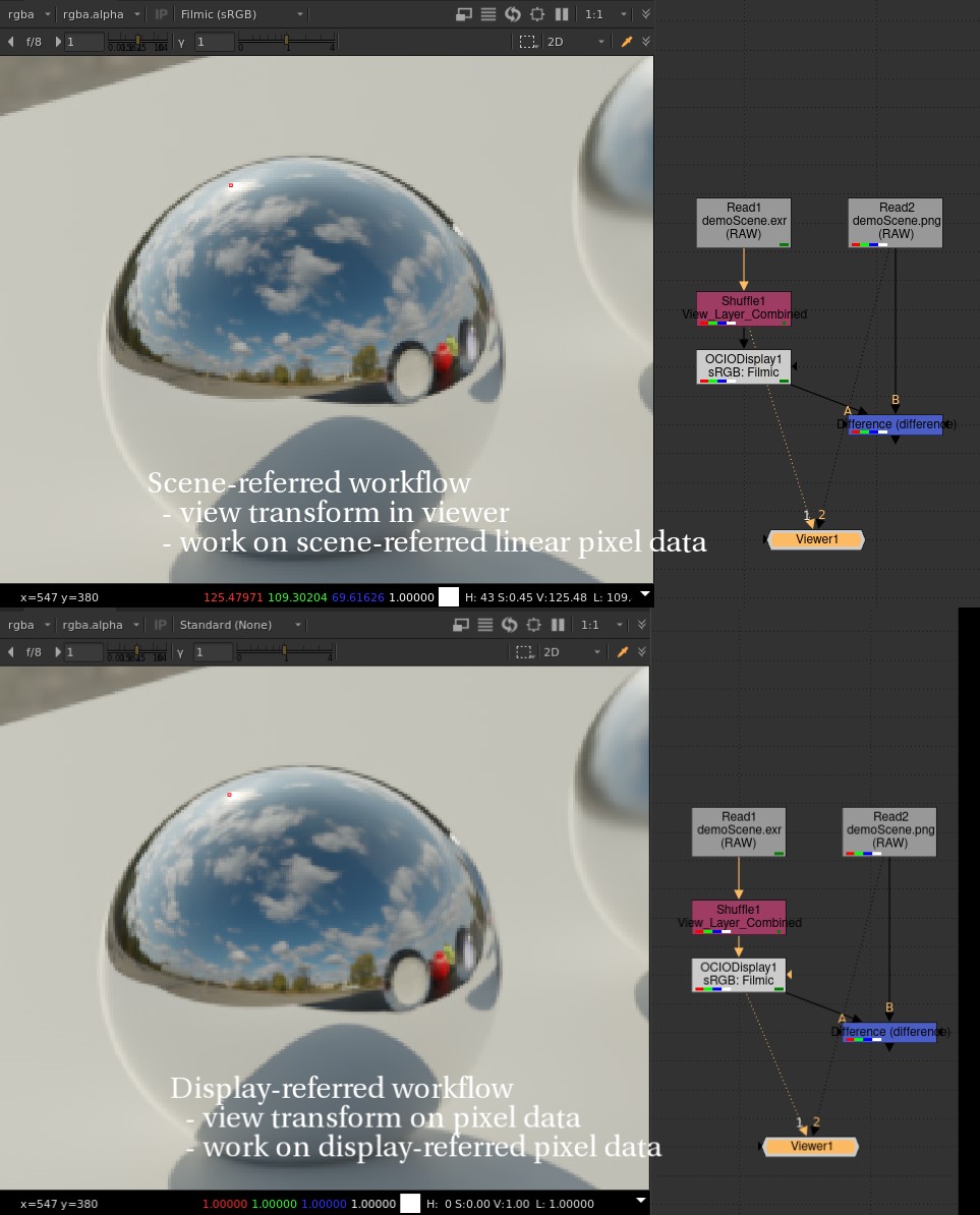
Just a note since we’re talking about it: The normal scene-referred workflow would be to
- load scene-linear exr images (cg render, camera-sourced images etc)
- work with scene-linear pixel data so that motionblur, defocus, convolution etc works correctly
- view our pixels with a view transform in the viewer
- bake the view transform into the image when rendering into a display-referred image format like a png or a quicktime.
I’m not sure which Filmic OCIO config you’re using… I’m using the one provided with the latest blender version, which seems to match the config in your zip file here: FilmingInComp/colormanagement/config.ocio
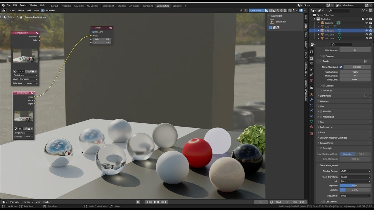
Here’s the nuke script. I’m setting the viewer to “Raw (sRGB)” to bypass ocio in the viewer code path.
set cut_paste_input [stack 0]
Read {
 inputs 0
 file_type png
 file ./demoScene.png
 raw true
 auto_alpha true
 xpos 526
 ypos -429
}
Read {
 inputs 0
 file_type exr
 file ./demoScene.exr
 raw true
 auto_alpha true
 xpos 400
 ypos -429
}
add_layer {View_Layer_Combined View_Layer_Combined.red View_Layer_Combined.green View_Layer_Combined.blue View_Layer_Combined.alpha}
Shuffle {
 in View_Layer_Combined
 name Shuffle1
 xpos 400
 ypos -351
}
OCIODisplay {
 colorspace scene_linear
 display sRGB
 view Standard
 name OCIODisplay1
 label "\[value display]: \[value view]"
 xpos 400
 ypos -303
}
I am glad I could help a bit. If it is okay with everyone, I would like to comment a few things from this thread. Because I think it is important that as a community, we all make the effort to be as accurate as we can.
I understand why you would say that, but you did re-open a thread that was “silent” for two years… to publicly say farewell to filmic. 
As my screenshot has shown, this is not true. I agree 100% that the first time you load the filmic OCIO config in Nuke, it does not work smoothly. But I would also say that it is common practice to edit/modify the OCIO configs to your needs. A simple notepad would do the trick. 
Also false, as my screenshot demonstrated.
Same here. I have access to the scene-linear values in Nuke, way above 1.
False. The very nature of the ACES Output Transforms (per-channel lookup, no gamut mapping and an actual clip at display !) prevents to do this. You will never get a match between different displays with ACES.
Have we proven this to you with our examples ? I hope so !
But Blender does support OCIO, correct ? So it means you can load an ACES OCIO Config in Blender, right ?
This is the best thing I have read in this thread. Thanks for writing this.
Please believe me when I say that I have been studying OCIO and ACES quite closely for the past two years and I have done my homework by writing everything that I have discovered in this article : https://chrisbrejon.com/articles/ocio-display-transforms-and-misconceptions/
Including how to modify an OCIO Config, it is actually super easy to do. Don’t be afraid to dive in !
Chris
Yep, it’s all good now. Thanks Chris. 
Holy heck… this will teach me for stepping away from the thread.
So with a little help…
THERE BE DRAGONS. Filmic Nuke.
Some changes I had to make to make sure that Nuke, which has been historically ropey dopey with respect to properly supporting OpenColorIO (Looks Foundry? Looks?)
Has not been extensively tested, but at least doesn’t crash ropey dopey Nuke.
Can you post the Natron screen grab please?
Ok, so now that it’s clear that we can use Filmic in Nuke, that doesn’t answer the original question of this post: How can I gat a plate in Blender without applying filmic on it. If you set your color management to standard, then your EXR will not look like the filmic render. The only way I coud do it is by adding a curve node to try to compensate. I’m very close to the original image except for the highlights. Any suggestions?
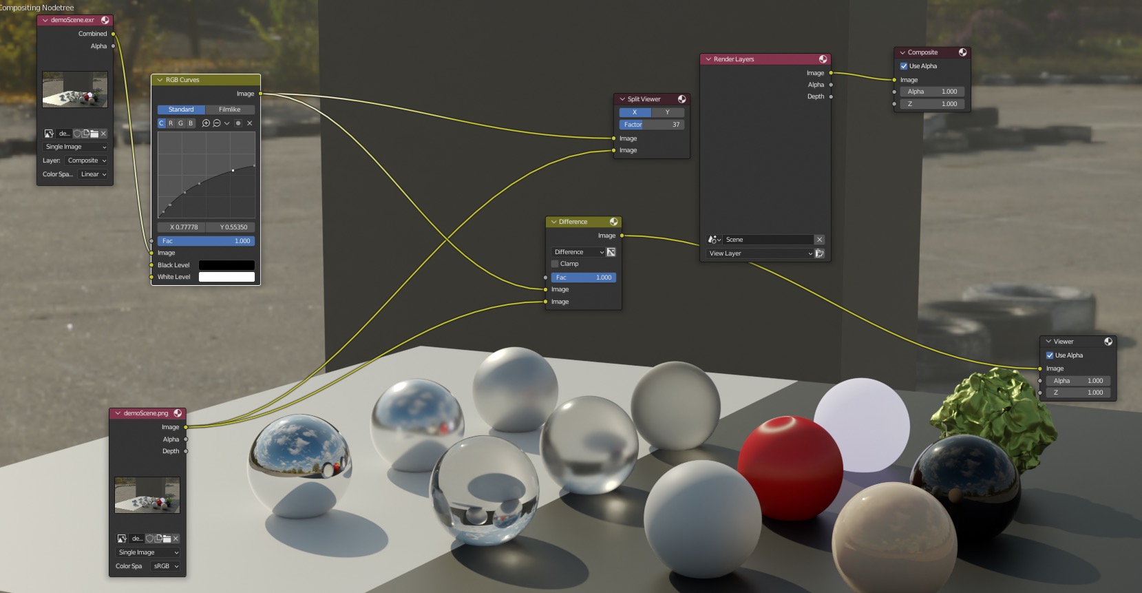
filmicInBlender.blend (887.9 KB)
Sure
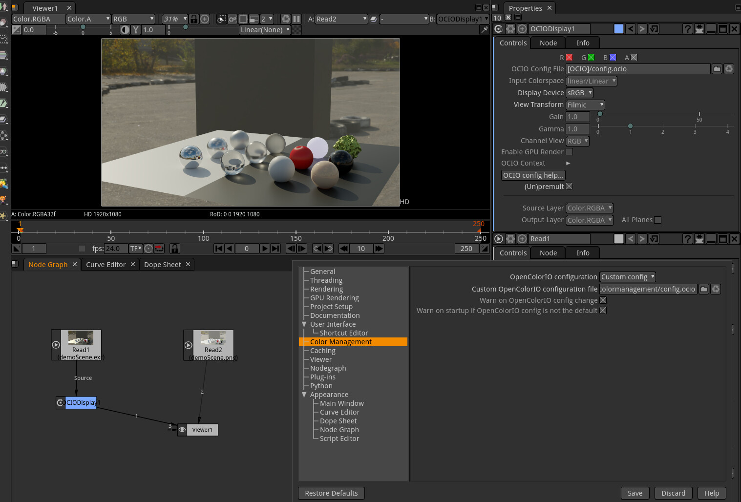
And here’s the text of a natron file that appears to kindof sortof be working repeatably.
- Go to settings / Color Management, set to custom config, point to the filmic ocio config.
- restart natron
- load exr and png images into natron
- set colorspace of png node to linear, so no colorspace transform is applied
- set viewer to linear so no colorspace transformation is applied.
- apply ocioDisplay node to exr image
- set to sRGB Filmic output
- the two images should match (assuming natron doesn’t crash or otherwise poop the sheets)
Note this is not how i would work, it’s just to show the two images match.
Unfortunately natron does not provide support for OCIO transforms in the viewer, you have to create a node and then move the OCIODisplay node around everywhere and connect it to what you want to look at and then look at the output of the display node. unusable. I asked them about this back in June 2018 and just got yelled at and told I was stupid so… oh well.
!!! We had a good discussion here but we never went down to the personal level.
Thanks for the screenshot. I will compare it with my recipe. The only reason I want it to work in Natron is that part of my audience use it. They don’t want to use Nuke Non-commercial or they want to go full open source.
I’m still working on filmic for Fusion. I can only do it with a transform so you need to make your color adjustments before the transform, which can be a problem if you need to integrate with sRGB images.
Nothing “has Filmic on it”. The plate arrives with its own encoding. By default for image files, that will be sRGB. To change the encoding, open the (ridiculous damn design) image viewer and the properties. Change the colour space encoding of the incoming encoding to whatever it is.
Many folks can pooch the output to display order on the nodes if they aren’t aware of the design of OpenColorIO’s Looks.
When Selan was designing looks, he designed it so that the Looks would take the open domain tristimulus values, go to some processing space, and then return to the starting point. This confuses plenty of folks when they first encounter it.
They expect the node order should be:
- Open domain →
- View →
- Look.
In reality, the proper order is:
- Open domain →
- Look →
- View.
In the broadest stroke sense, think about two classes of colour in applications:
- Colour data. Think of it as clay.
- Image data. Think of it as a painted, glazed, and kiln baked cup.
When we have rolled information through any image formation chain, we end up holding something that was once wet, sculpted clay, subsequently dried, then painted, then glazed, and finally, put into a kiln. The cup is a “completed work” when it comes out of the other end of that process, and bears only a glimmer of similarity to the medium that inspired it.
Much like the clay and cup, an image exists in a similar relationship to the stimulus data that inspires it. Clay can arrive in different packaging that serves a different need than the packaging for a finished cup, and in a similar way, file encodings could be considered different packagings for different contents.
——
In Blender, and most DCCs, we are saddled with crappy computer displays as a “window” into emulated models and systems and math / code nerd crap. It’s a peek hole into a room constructed entirely of numbers.
In the “View” of those numbers, the thing that shapes what those numbers mean, there can be only one “View” for any given perspective of the “Model”. In the above video, there can be only one “View” for two different internal “Models”; Open Domain colour stimulus encodings from an EXR, and an image baked through Filmic.
When we are viewing the open domain colour stimulus encoding from the EXR, we must view it differently than the final, fully formed image encoding.
One is clay in a bag. The other is a cup in a store box.
TL:DR: It is impossible to view two completely different representations of an internal model in parallel, without opening up two completely different views of the data. This is not any different than wanting to see the side view and top view of a model simultaneously in the same viewer.
——
Speaking to the larger question, what I think you are getting to is “OK… how do I take my fully formed Filmic image and work with more open domain stimulus data?” If this isn’t what you are getting at, then apologies for my misinterpretation and the following explanation.
——
What would we say if someone tried to put a clay handle on a kiln baked and glazed cup? Pretty challenging! The material has fundamentally changed forms, from the clay that was used to form it, and the material is radically different.
The short answer is that we would say “Sorry sir, that’s a cup, not clay.”
The longer answer is “We could crush the cup up into the dust, including the bits and pieces that shouldn’t be in there, and maybe mix it with some glue and water, and maybe it might be sort of a substance that you could slap your clay onto?”.
Another answer could be “We could process your clay in precisely the same way and try to then glue that handle onto your cup?”
That is, either we work with the fully baked cup and distort the clay into kiln dried pieces, or we try to work with the clay, and try to smash the cup up and mix it with glue to get something closer to clay.
Neither “solution” here, is very good as we can all likely agree.
——
I’ll leave it at that for now, given that explaining how that last paragraph can happen is predicated on appreciating the radical and untenable situation of working with cups versus clay.
I know that I don’t have to point out the shortcomings of Blender’s idea of a compositor, but perhaps the addition of CST nodes is what is necessary. The main issue that I see from your video is that Blender applies these transforms globally, where they should be applied locally on a file by file case.
For instance, if a proper CST/Gamut Remapping node existed in Blender, it should be possible to convert all of the incoming files to a common denominator gamma/color space and then apply the desired ODT at the end of the chain – which in theory should yield the same results (but likely won’t match 100% due to limitations of the transform math applied to different incoming data, but that’s like trying to make a fast food burger taste identical to a restaurant one).

Well, isn’t that what ACES is all about? ACES being the common denominator. Linearize anything that comes in in ACES, do your comp, output to whatever is needed?
So if it’s not possible, how am I supposed to do any compositing with an sRGB plate and EXR renders in Blender?
It’s easy in ACES in Nuke though. I just need to set the color space of the PNG to sRGB and ACEScg for the EXR and that’s it.
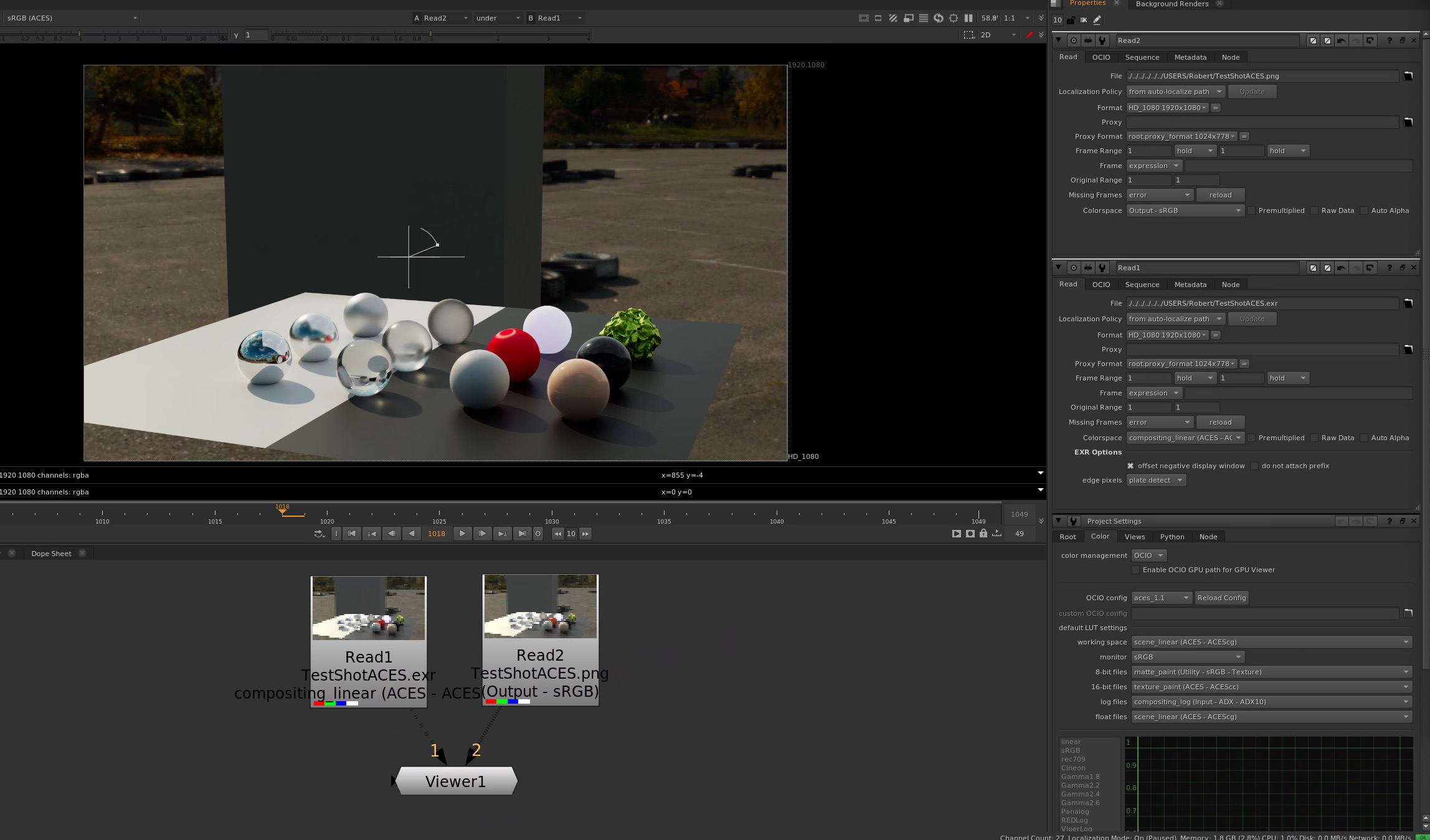
Sure, except according to @Chris_Brejon 's findings, the big problem is the ACES ODT which clips everything to bits.
I can’t believe you gave me grief about AfterEffects and yet here you are trying to figure out how to comp in Blender! 
I would say don’t use Display Referred sRGB plates and opt instead to convert the footage to EXR before hand. Don’t get me wrong, I completely understand the point you’re trying to make, and you’re absolutely right. This is an issue that needs solving for sure.
Personally I am trying to figure it out myself, I was all set to just switch my entire workflow to ACES (my New Year resolution…I know I need better resolutions). While I am avidly trying to absorb Chris’ insights, I am also rushing to gear up for a rather complicated film project that requires a solid pipeline which I haven’t quite figured out yet!
https://developer.blender.org/D12481
edit: also this one https://developer.blender.org/D12520
will help with some issues, but not all
Oh! That was you!
Personally, I don’t care because I’m in full ACES workflow but I’m doing all this for my viewers who don’t necessarily have an IO team that will convert, setup and pre-chew everything for you before you even open Blender or Nuke. And even if you convert your plate to EXR, that won’t fix the problem in Blender.
We did! Talk to me on my Discord server. 
Hello guys,
I hope you’re doing well ! Thanks for the video Bob, that was cool to see your question like that in “real-time”.
Sorry to be a pain in the ass, but in your example, you set the IDT to “Output - sRGB”, not “sRGB”. It means that you use the Output Transform as an Input Device Transform. I would say this is a workaround more than a solution. But this is exactly what came to my mind when I saw your video.
So how can we do that with Filmic ? Once again, by modifying/editing the OCIO Config. Here is a little explanation about it.
As you certainly know, you can save a png/jpg from Nuke with “Filmic” embedded/burnt-in directly in the file, like this :
- Read node in “scene_linear”
- OCIODisplay set to “Apple P3 + Filmic High Contrast”
- Write node set to data (Non-Colour Data), so you don’t get “Filmic” applied twice.
(I had a beautiful screenshot to illustrate this but new users can only upload one media per post).
But what if I just want to set the Write node to the colorspace that I want, which is in this case : “Apple P3 + Filmic High Contrast” ? Well it does not exist by default, so let’s create it in the OCIO Config. I will just open the Config in notepad and duplicate this block of text :
  - !<ColorSpace>
    name: AppleP3 Filmic Log Encoding
    family:
    equalitygroup:
    bitdepth: 32f
    description: |
      Log based filmic shaper with 16.5 stops of latitude, and 25 stops of dynamic range with Apple P3 primaries.
    isdata: false
    allocation: lg2
    allocationvars: [-12.473931188, 12.526068812]
    from_reference: !<GroupTransform>
        children:
          - !<ColorSpaceTransform> {src: Linear, dst: Filmic Log Encoding}
          - !<ExponentTransform> {value: [2.2, 2.2, 2.2, 1.0]}
          - !<ColorSpaceTransform> {src: Linear, dst: Apple DCI-P3 D65}
          - !<ExponentTransform> {value: [2.2, 2.2, 2.2, 1.0], direction: inverse}
    to_reference: !<GroupTransform>
        children:
          - !<ExponentTransform> {value: [2.2, 2.2, 2.2, 1.0]}
          - !<ColorSpaceTransform> {src: Apple DCI-P3 D65, dst: Linear}
          - !<ExponentTransform> {value: [2.2, 2.2, 2.2, 1.0], direction: inverse}
          - !<AllocationTransform> {allocation: lg2, vars: [-12.473931188, 4.026068812], direction: inverse}
And modify it this way :
  - !<ColorSpace>
    name: AppleP3 Filmic Log Encoding High Contrast
    family:
    equalitygroup:
    bitdepth: 32f
    description: |
      Log based filmic shaper with 16.5 stops of latitude, and 25 stops of dynamic range with Apple P3 primaries and High Contrast Look
    isdata: false
    allocation: lg2
    allocationvars: [-12.473931188, 12.526068812]
    from_reference: !<GroupTransform>
        children:
          - !<ColorSpaceTransform> {src: Linear, dst: Filmic Log Encoding}
          - !<FileTransform> {src: Filmic_to_0.99_1-0075.spi1d, interpolation: linear}
          - !<ExponentTransform> {value: [2.2, 2.2, 2.2, 1.0]}
          - !<ColorSpaceTransform> {src: Linear, dst: Apple DCI-P3 D65}
          - !<ExponentTransform> {value: [2.2, 2.2, 2.2, 1.0], direction: inverse}
    to_reference: !<GroupTransform>
        children:
          - !<ExponentTransform> {value: [2.2, 2.2, 2.2, 1.0]}
          - !<ColorSpaceTransform> {src: Apple DCI-P3 D65, dst: Linear}
          - !<ExponentTransform> {value: [2.2, 2.2, 2.2, 1.0], direction: inverse}
          - !<FileTransform> {src: Filmic_to_0.99_1-0075.spi1d, direction: inverse, interpolation: linear}
          - !<AllocationTransform> {allocation: lg2, vars: [-12.473931188, 4.026068812], direction: inverse}
So what are the changes exactly here ? Here they are :
- Change of the name
- Change of the description
- I added the “High Contrast” spi1d Look both in “from_reference” and “to_reference”.
Now, let’s go back to Nuke. I can write the png directly with the Write node to embbed/burn-in “Filmic” :
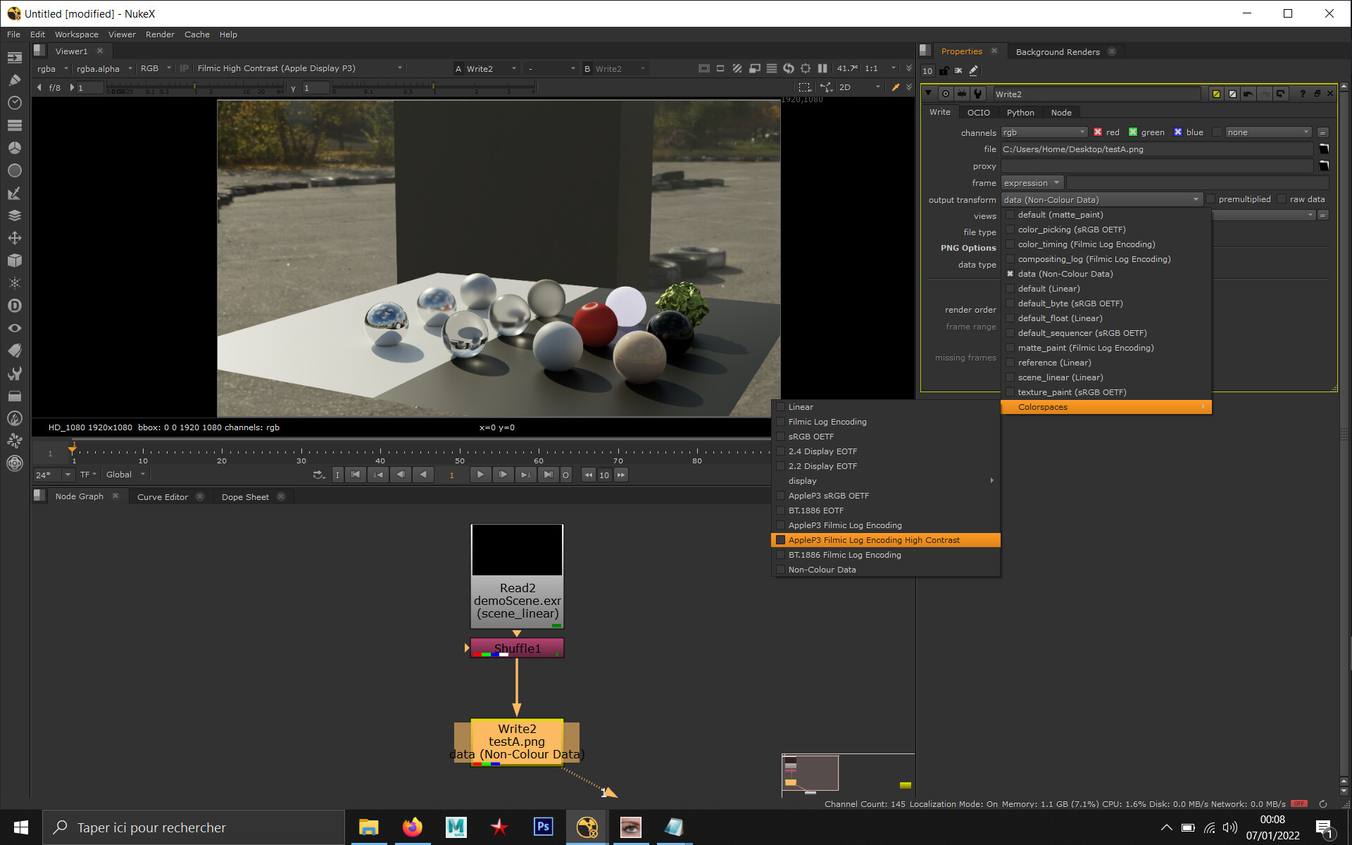
No need for an “OCIODisplay” node this time. The new colorspace appears directly in the “Write” node. And this finally leads us to our solution… You can now load the png file with this colorspace, just like the ACES workaround you are familiar with.
(I also had another beautiful screenshot to illustrate this… bummer !)
I have checked and it matches pretty well I would say. Please bear in mind that this roundtrip is not lossless and it is just a workaround, not an actual solution.
My only doubt with my mini-tutorial is this line :
- !<FileTransform> {src: Filmic_to_0.99_1-0075.spi1d, direction: inverse}
Should it be this ?
- !<FileTransform> {src: Filmic_to_0.99_1-0075.spi1d, direction: inverse, interpolation: linear}
I have tried both and both seemed to “work”. But to be completely honest, I am not 100% sure on which makes more sense.
Thanks, but I haven’t found anything. I am just the guy who listens and takes notes. The “clip” is actually in the ctl code :
    // Handle out-of-gamut values
    // Clip values < 0 or > 1 (i.e. projecting outside the display primaries)
    linearCV = clamp_f3( linearCV, 0., 1.);
By the way, did you guys know that “Filmic” was used on this short film ? Pretty impressive !
Hope it helps !
Chris
But it’s working
That’s also a workaround
Apple P3? Is it the same as DCI-P3? That not as wide as REC2020 or ACES. Why P3?
Nice
That’s cool
Thanks!