[1] The renderer does not recalculate the light probe with eevee.
[2] Set another camera for orthographic projection.
[3] Very simple Freestyle is added.
[4] Render with background transparency and place it as a background image on the camera set in [2] .
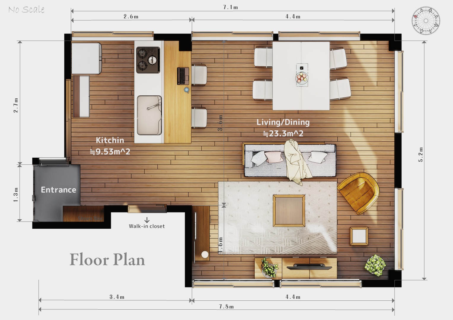
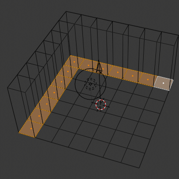
[5] Use the floor object to fill in dimension lines with measureIT.
[6] Write the dimension value and text with the text object.
Hi,
Interesting work, getting a rendered plan from Blender.
What is your point, #1 above? please explain
Could you please elaborate on this process? Would you please share the background image that you created with Freestyle?
So you have a plane as a floor, unwrapped the texture for the wood and extended the UV map out in white areas where you fill in the dimension lines? Would you please share a screenshot of the floor object singled out? (local view)
Did you use camera clipping to “look into” the room without affecting the lighting inside?
I’m not really clear about what you mean - sounds like you rendered it once, then placed the image as a background in another render. But why would you do that?
Thanks your message.
I asked various questions, so I made a tutorial video.
I don’t speak English, so I have no audio.
Please do not laugh because it is the first video made ^ ^
I am not really sure about the cause of the problem [with black walls] because I have a dozen of ideas.
Perhaps there would be such cases.
Wall must be a surface. As for example the wall must be a filled rectangle. No hollow rect / parallel lines.
Normals point to the opposite direction. You would have to make sure rotation of model is [0,0,0] and scale is [1,1,1] . Then you would have to make sure that the surface of the wall (2D mesh) is pointing up (not down). In edit mode check the view option to show normal lines.
Perhaps if you use modifier (eg: Solidify) it might have some weird parameters that cause the problem. Such as “Flip Normals” or “Material” index. So you might have to check and test one by one each parameter.
Last but not least. The most safe solution is to have two wall models. One wall model will be the “TopDown” the other model “3D Walls”. And that way you can control which one you want to render in each view. You would be very safe with this solution because you would expect 100% how the 2D model supposed to look like.
Thanks your message.
This English sentence is a little difficult and my interpretation may be wrong.
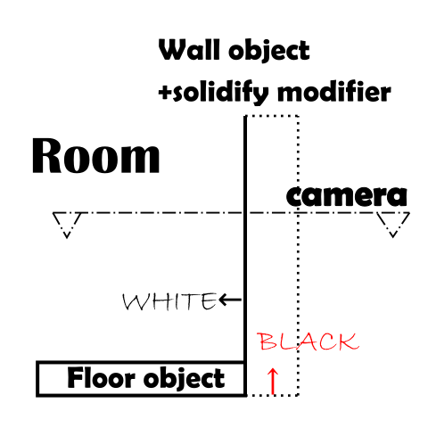
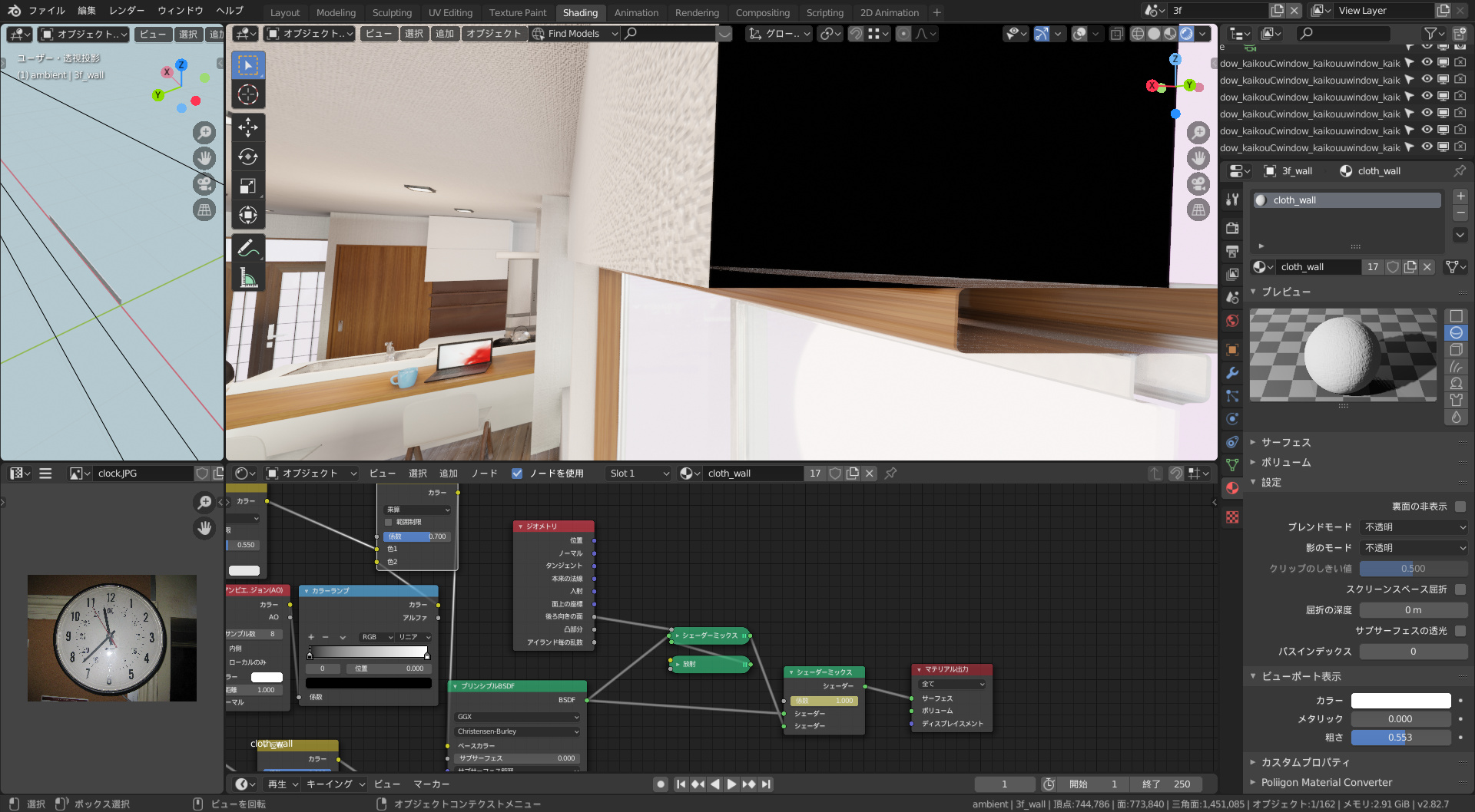
There are things to keep in mind when modeling. To place a floor object inside a wall object.
Now, as shown in the figure below, the natural black surface (back) will be reflected on the camera.
There is another small trick that looks like this, so please take a look if you like.
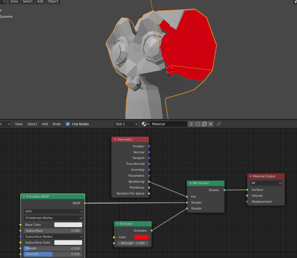
OK, I had a peek at that shader you created and it seems that you use the LightPath technique. I am not sure about how the material works, I would have to spend many hours to test it and understand it. But sure since is difficult material something might be off and cause the problem.
I am not familiar with LightPaths though I have seen some tutorials. As for example having the material setup correctly, say the default color is red, place a transparent object infront of the camera and then material becomes blue. This is something that works good for light paths.
. https://www.youtube.com/watch?v=NhOdnOow6DY
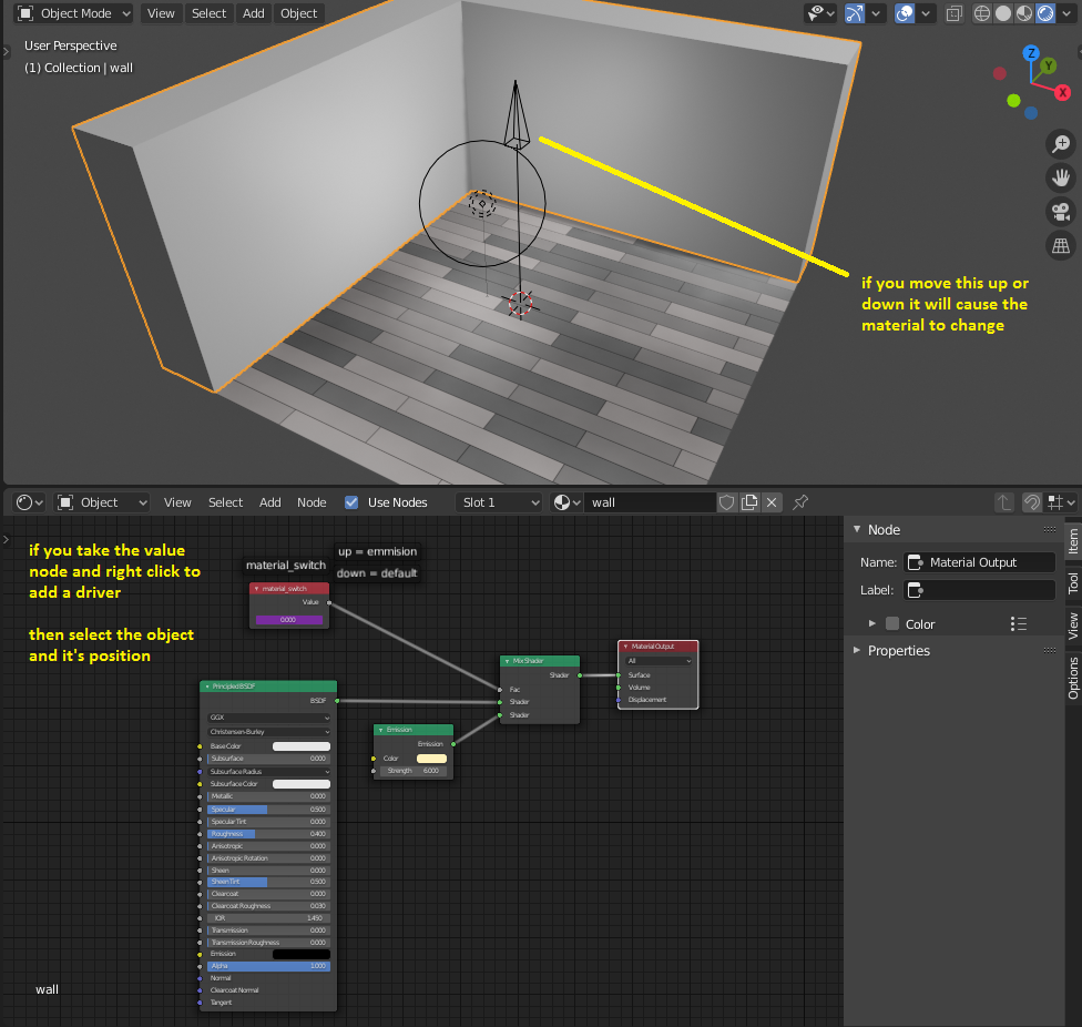
More or less the most simple version I prefer is to control the material index by a special value. However this value is controlled by a driver. Place an object in the scene and use the position (or something else) as a switch.
Thanks for checking a lot, and even the download files.
I am very impressed with your deep thoughts, and I learned how to use “value input”.
It is very emotional that I take this method (geometry input).
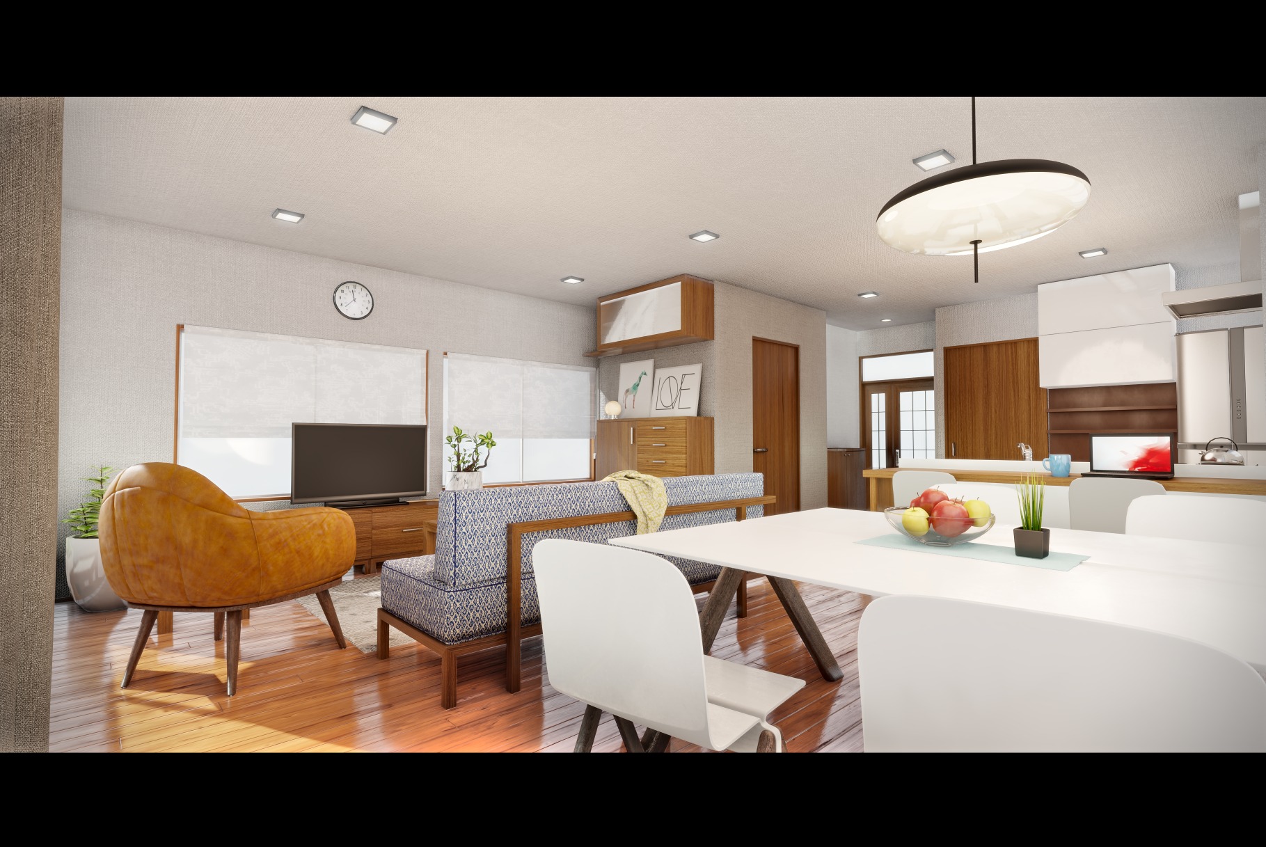
As you can see from the reference photos, the material on the interior surface does not change even if I release the camera view for the floor plan during the work.
I am immersed in the amazing real time preview on EEVEE and fun!
In that sense, it may not be necessary to keymap the FAC of the mix shader.
Thanks a lot!
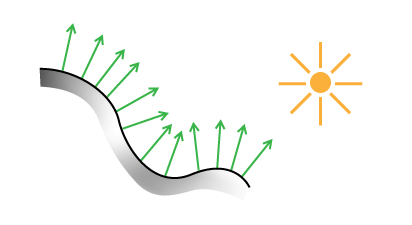
The problem here is that all renderers do this. They need the surface direction (surface normal) to be visible from the camera direction (camera normal) and some lights to bounce off the surface.
So you have LIGHT+SURFACE+CAMERA all work together to make things look good.
If for example something is not present or points to the opposite direction things won’t look good.
As for example in the example file I make sure that the wall geometry has filling and is not hollow. Then I use a solidify modifier to extrude upwards. That way the renderer can work nicely.
Perhaps if you want to share a small part of your file (a simple wall) so I can look at the material.