I have found a simple node setup to generate a procedural hexagonal pattern! If you don’t care how it works and just want the file, scroll to the bottom.
I started with the solution to this question on blender.stackexchange:
Full credit to Robin Betts, who posted a solution and without their hex coordinates nodes this wouldn’t work!
however, this only created round cells in a hexagonal pattern. I wanted to have sharp hexagons with a linear gradient from center to edge.
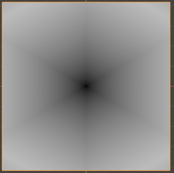
My solution was to create mirrored a 60° triangular mask:
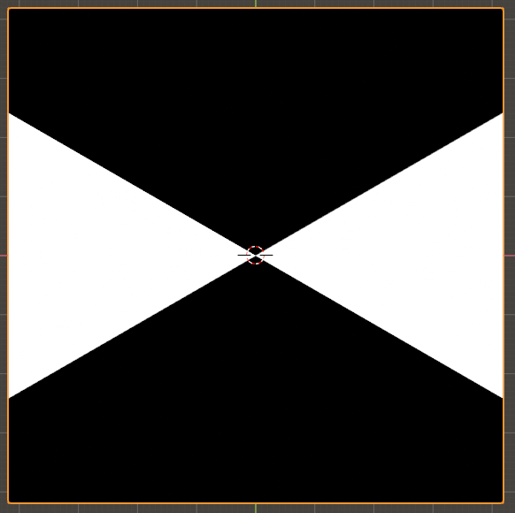
I did this by taking the object X coordinates twice, once rotating it 30° and the other -30°.
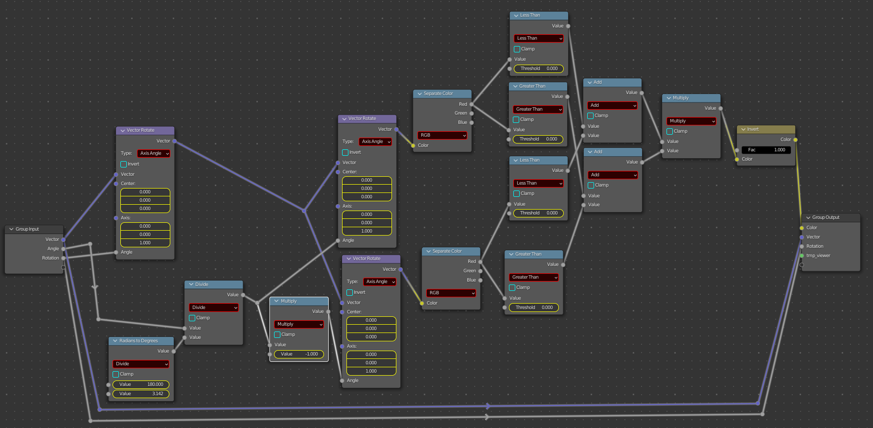
I then fed these two angled gradients through a series of greater than/less than nodes, adding them together then inverting to get the above double wedge with this node group labeled “wedge”
Note how the angle and vector values are passed through to the output, they will be needed for the next group.
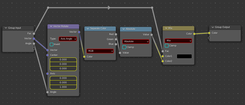
Next, I needed that linear gradient so I once again used object X coordinate, this time using an absolute math node to exploit the symmetries of hexagons. Using the color output from the wedge node as a mask, I got one of these for each rotation:
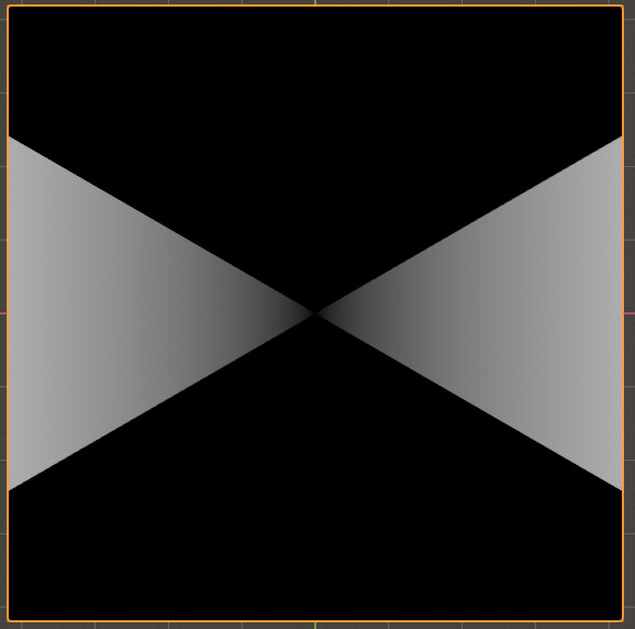
using a much simpler node group labeled “Gradient”:
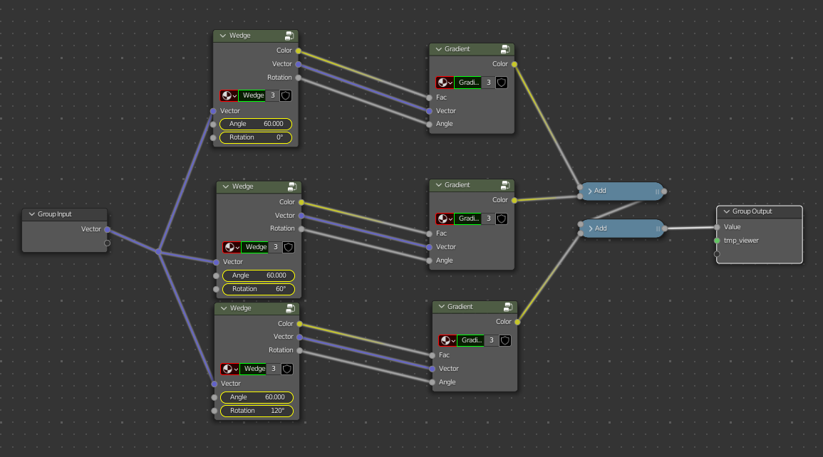
Then, putting it all together to get this
using this setup in a group labeled “Hexalinear”:
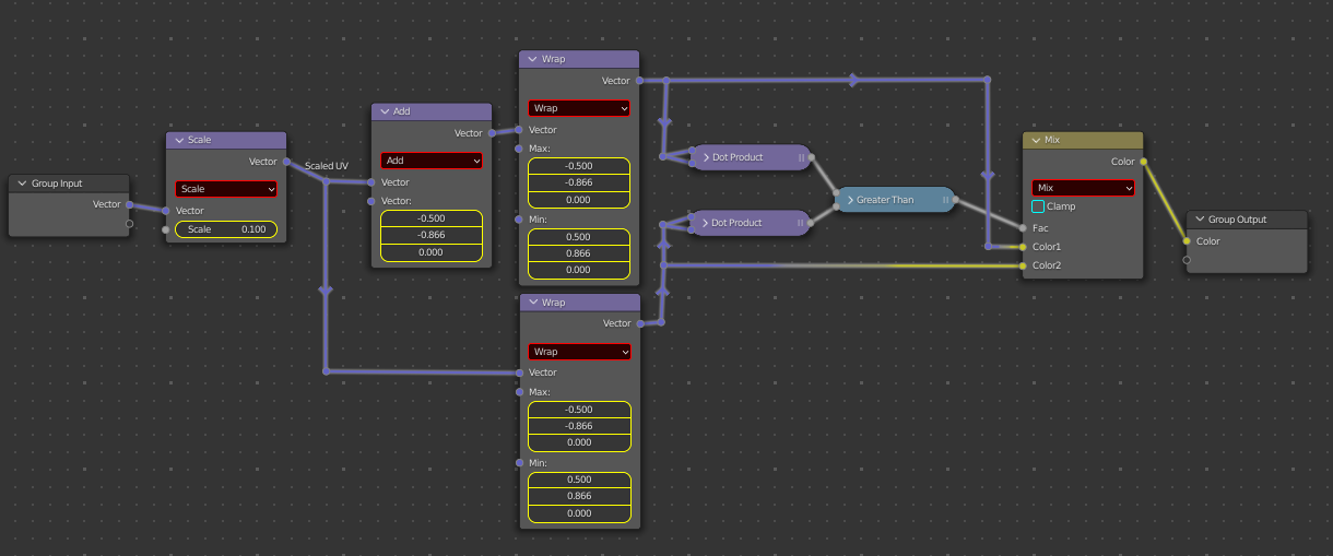
The next step (Actually, I did this first) is to use the hex coordinates from Robin Betts’ solution on Stackexchange, linked at the top of this post.
It turns out all I needed was the very first part so I deleted the rest and made a group labeled “HexaCoords”:
Although I admit I don’t really understand the math here, this setup quite handily creates this: (scaled to
0.60 so you can see the pattern)
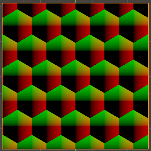
which, when used as the vector for the HexaLinear node results in:
Success! Putting that output through a “greater than” math node produces a sharp hex pattern with a full range of thicknesses, determined by the greater than node.
Then I decided to take it to another level: add a “roundness” value.
I decided not to use Robin’s solution as it seemed a bit too complicated and I didn’t need any randomness.
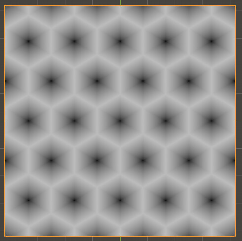
So, this solution is much easier to explain. I simply took the vector distance of the object coords to make the familiar soft circular gradient and made copied for each of the six points of a hexagon. Then, I added them all together and used a clamped map range node to remap the values to 0-1, all in a node group labeled “HexRound”
(All the values in the distance nodes are some combination of +/- 0, 0.5 and -0.28867)
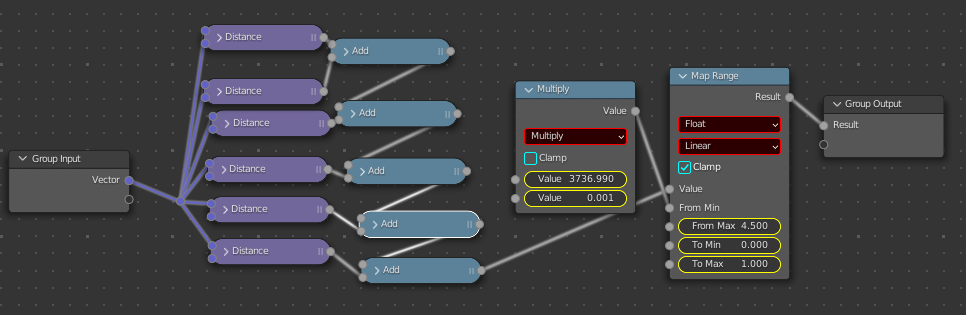

I don’t know why the map range “from max” value ended up at 4.5. I had to manually zoom all the way in and adjust by hand to get to that value. I would have thought I need to remap 0-6 to 0-1, since I am adding up six different 0-1 value maps. Oh well.
(as I am writing this I went back and noticed that the HexaLinear group needed an additional map range node to remap 0-0.5 to 0-1. It looks like the edge values at the edges don’t go all the way to 1 without adjustment)
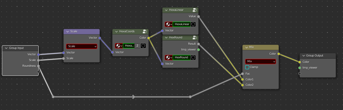
Now all I needed to do to adjust the roundness was to mix HexaLinear with HexRound, sliding the factor to get the desired roundness. All put together in one node labeled “Hexagons”:
Used with a greater than node set to .833 I get this nice range of shapes:
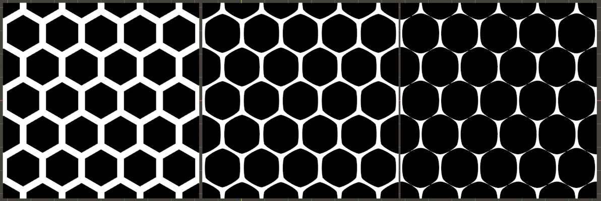
If the threshold is set anywhere higher than 0.833 then the round cells break apart, leaving behind a grid of caltrops (which you may want)
(Also, I’m not sure why the vertical edges are so much thicker than the angled ones. If anyone knows why that is and how to fix it, I’d greatly appreciate the knowledge!)-EDIT: I solved this problem. I was using the wrong values for the coordinates in the distance nodes.
Anyways, here’s the .blend file for anyone to use!
HexSharp02.blend (3.9 MB)