Hi,
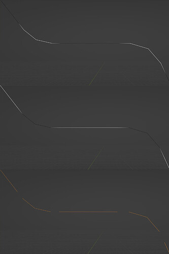
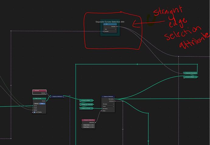
I am currently working through a problem where I am trying to split my edges based on a selection. I want to then join them back together seamlessly after splitting the islands but when I invert the selection I always get this gap as seen in the attached image.
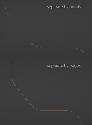
I know that I need to expand the selection of the curved areas by 1 vertex to close this gap. To do this I usually would blur the attribute and then use a floor node. However in this situation, because the straight part of the mesh is a single edge connected by 2 vertices, as soon as I grow the selection of the curved section it encompasses the flat edge as well. I’ve tried setting the separate geometry node to both edge and point modes and both do not seem to give desired results.
(I have thought of subdividing the edge to add a vertex in the middle of the flat edge before expanding the curved areas selection however this wouldn’t be ideal for what I’m trying to build…)
I would really appreciate some advice on how to tackle these kinds of problematic selections.
Thanks!
I think using the Edge domain on the Separate Geometry node is the right idea.
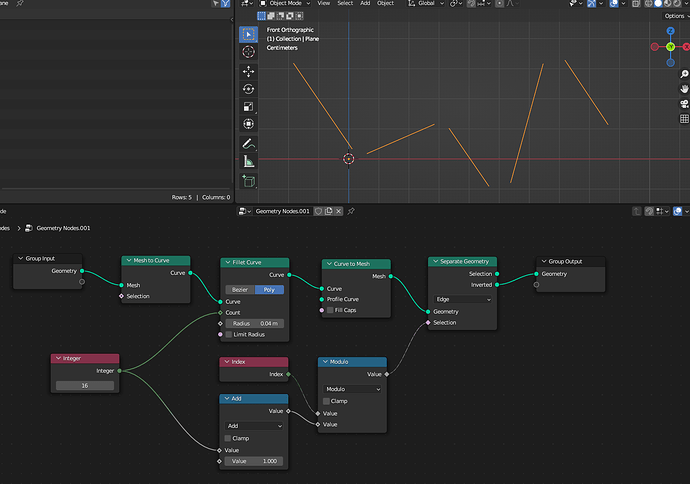
Try it like this:
1 Like
Thanks for the response. Unfortunately the edge method also produces the same issue. The edge method expands the selection as desired but it will still encompass the straight area and joins into the next curve section. I specifically need it to be a perfect inversion of the straight version so I can join them back together seamlessly.
It feels like the only workaround might be to add that vertex in the middle of the straight edge so there is some kind of boundary between each curve section so the selection can be expanded and still be isolated to only the curve areas.
You probably didn’t add a Convert Curve To Mesh node, before the Separate Geometry node.
A curve doesn’t have edges - that’s why it’s probably not working as expected.
1 Like
Just confirming that I do have a curve to mesh node before the separate node.
1 Like
I can confirm that mesh edge splitting works:
It has to be something else - like are you using both outputs from the Separate node or are you using another Separate node with different selection logic?
1 Like
Can you post your blend file please?
Edit: Do the straight lines consist out of multiple lines? Or is it just one single straight line?
The straight lines are just a single line/edge.
Sure, heres the blend file. Thanks for taking a look 
PipeGen_v31.blend (2.2 MB)
I think yours works because your selections are far apart from each other. If you had 2 selections right up against each other with only a single edge between them it would bridge the gap automatically in the same way that when you select 2 verts, it automatically selects the edge with it. Same concept.
Check out the scene file I attached.
OK, i’ve looked at your file and there are multiple problems in your setup.
-
The straight parts do (!) consist out of multiple edges. It happend when you created the points for the flanges. You can basically skip the whole “Move Fillet Vert Back to Position” section in your setup for the extrusion and only use the newly created points for instancing.
PipeGen_v32.blend (234.0 KB)
-
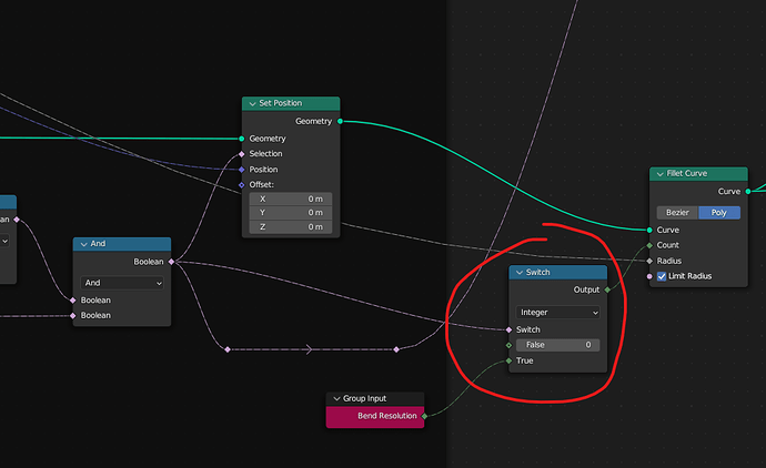
Because you have these additional points in your curve, it will create even more additional points, when you add the final Fillet Curve. If you really need the loop in the extrusion, i would suggest to use a Switch node set to Integer, to only make the fillet where you need it:
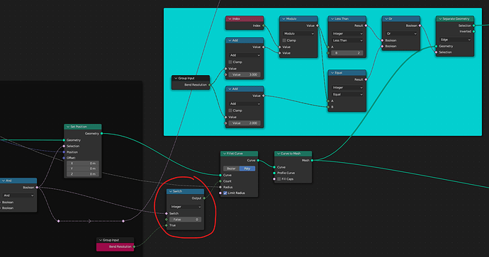
This is at the end of the “Move Fillet Vert Back to Position” section. But you would also have to update the seperation method like so:
There are probably better ways to select the edges but this is just what i’ve come up with 
But to be honest, i wouldn’t create the loops in the extruded area and only use the points for instancing
Little tip: Use the Spreadsheet! It might seem useless when starting with Geometry Nodes but it’s super helpful! You would have seen, that you have more than 3 straight edges, when you set your “Bend Resolution” to 0.
1 Like
Thanks a lot for for checking out my file.
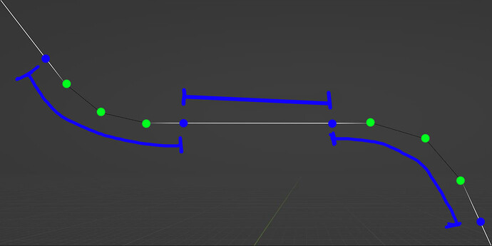
I think you may have misunderstand what I am trying to do though, I realise that the straight line is made up my more than edge (sorry, I should have been more clear in my previous message) however, I am trying to expand the curved areas to to use those extra verts on either side (see attached image). Its important for my setup as this is where I am planning on splitting the geometry into separate parts / UV islands. The reason for this is that if you subD a tube with just a simple fillet without support loops (or splitting the geo) on either side it wont stay perfectly straight (especially on sharp angles) and will not align with the flanges nicely. I also don’t want the flanges to sit perfectly on the ends of the curved areas as I want to control the offset on either side of the fillet for extra control ideally.
I had a little play using method you suggested in the second image but using that method changes the selection based on the resolution of the fillet it seems. The selection should stay consistent regardless of the bend resolution.
Ahhh i think i get it! This should do the trick:
With the
Math - Modulo node, we divide the indices of the edges into repeating chunks. Because we have 3 “straight” edges for every “fillet”, we have to add this value to our divisor.
In this example, the “Bend Resolution” was set to 2. So we get a pattern that looks like this: 0 (straight edge) → 1 (additional straight edge) → 2 (fillet) → 3 (fillet) → 4 (additional straight edge). If we have such a pattern, we can simply use a
Compare node to separate the desired edge (0, in our case).
Hope that makes sense!
2 Likes
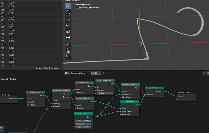
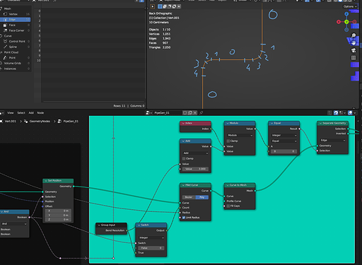
Thanks for the suggestion. Modulo would also be a good way of isolating the straight edge. however this brings us back to the original problem. I don’t have an issue isolating that straight edge as I already have an attribute for it (as seen in the attached image).
I am wanting to isolate the curved areas + the vertex on either side without that straight edge in the middle.
The Separate Geometry node outputs a Selection and the Inverted. Isn’t that exactly what you’re asking for? The Inverted output?
Edit: Just to be clear: This is what the outputs from the Separate Geometry node from my last post look like:
White is the
Selection (straight middle edge) and black is the
Inverted
2 Likes
