In trying to correct the parallax effect where a plane pretends to show depth, I think this Attribute for this Node can help me Rotate the plane but I need to understand what Incoming means and can find nothing useful. What does Incoming mean? The docs use spare terminology that raised more questions ![]()
Incoming
Vector pointing towards the point the shading point is being viewed from.
Here I assume “the point the shading point is being viewed from” means the location of the previous bounce, but I don’t really know for sure
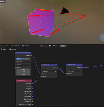
IIRC it’s the vector pointing from the geometry position (shading point) to the camera location (point being viewed from):
![]() It’s like a weird plane through the screen view. ?? I used it to Factor a mix shader with diffuse and emit. Emit was activated and the Object’s + 1, 1, 1 position lit up but not based on the camera. The Object’s 0, 0, 0 (based on the BOUNDING BOX) was diffuse. And the difference was sudden; a Color Ramp couldn’t really affect the color of the EMIT portion.
It’s like a weird plane through the screen view. ?? I used it to Factor a mix shader with diffuse and emit. Emit was activated and the Object’s + 1, 1, 1 position lit up but not based on the camera. The Object’s 0, 0, 0 (based on the BOUNDING BOX) was diffuse. And the difference was sudden; a Color Ramp couldn’t really affect the color of the EMIT portion.
This is a very odd Attribute. Can anyone else help clarify?
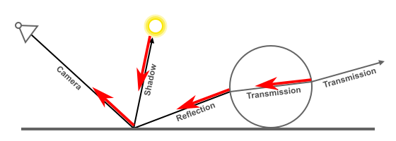
That’s just for camera rays… Shadow rays and indirect/bounced rays also have an Incoming vector, and as Hadriscus explained, are pointing to the position where the ray was spawned.
Starting from the begining: A ray from the camera is sent to the scene, it’s direction is equal to -Incoming, which is pointing to the camera. After hitting an object, a Shadow ray is sent to some light, and some other rays are sent to the scene depending on the BSDF that was hit. These new rays have a direction (as all rays have), and it’s equal to -Incoming (a new vector for each ray). And the process repeats until the last ray hits a light, or the background, or it becomes to dimm to carry any light at all.

All red arrows are Incoming rays.
Thank you for your time explaining!
How is this shader best used? Almost directly as the factor in a mix or manipulated by math to control vectors farther down the line in a node?
It’s one of the few Geometry > Attributes available to volumes too. I thought that might be a clue to a best-use scenario.
Unless your knowledge of shading and vector math is good, I advise you not to touch the Incoming vector. It is there, for very specific effects, and should only be used if you know exactly what to do with it; and internally it’s also used in some other nodes (Bsdfs, Fresnel, LayerWeight, etc), so you can use those instead.
I don’t know what you’re talking about. The Attribute node’s purpose is to get access to variables stored in specific domains… like vertex/edge/face/voxel attributes stored in the mesh/volume/curve (Geometry); or values from the Object, like ‘width’ or ‘scale’; or even values from the scene/view_layer, like ‘gravity’, etc.
It has nothing to do with rays.
Alright, so this is only valid for camera rays or…? the manual definitely could use a clearup
Ok I should read everything before barging in… looks like my initial intuition was right… I stand by my statement that the manual could do better in that area
That’s easy… make a clone of the Manual project, change it, and make a Post Request with your changes. ![]()
Per the docs: “For volume shaders, only the position and incoming vector are available.”
But even I don’t know what I’m talking about except that your help has shown me how INCOMING is above my paygrade! I appreciate your pitching in.
I think the manual’s target reading level is sometimes aimed at the new to intermediate user which typically helps me but this is one subject I can’t parse for an easy chat. (EDIT) Maybe if you do get in there and clarify, a link defining “shading point” would be a subtle start?
Good advice, yea I’ve already been at it for the past few minutes, following this https://docs.blender.org/manual/en/latest/contribute/install/windows.html
@HelloHiHola I think some parts of the (Cycles) manual assume you have a thorough understanding of path tracing and the lingo behind it. Which is the case of maybe 3% of Blender users. Or maybe 8%. One of those
This is simply because in a volume you don’t have a ‘surface’ (triangles)… In that sense, all properties of a surface don’t work there.
- Normal : vector representing the direction the surface is oriented
- Tangent : another vector, perpendicular to the Normal and by default to the Z axis
- True Normal : the Normal vector of the triangle being shaded, without vertex interpolations
- Parametric : the U, and V coordinates of the triangle (W can be infered by the first two)
- Backfacing : a boolean that represents if the face is being hit from the front, or from the back, and it’s equal to
dot(I, Ng) < 0 - Pointiness : The change of Normals between one triangle and its neighbours
- Random per Island : a random float, for each surface disconnected from the others.
Leaving just the Position, which is some point inside the volume (the one being shaded), and the ‘Incoming’, which as said above, is just the direction the ray travelling through the volume is coming from.
Sorry maybe you read the post that I deleted.
I deleted it because it was not “correct”, although it is a way of changing colours/shaders depending on viewing angle, it was not the correct explanation.
Secrop Thanks for this answer it explains what was bugging me that I could not get a pure blue from the incoming vector.
I would not go that far.
The incoming vector is interesting especially for parallax shaders and portals.
“Don’t push that button” always makes me want to push it!
There’s an ‘Unless’ before that sentence. ![]()
If they are exposed to the user, they are supposed to be used. My point above, was just: “if someone doesn’t know exactly what they are trying to do, perhaps it’s better to leave them alone”.
In fact, a few posts later, I mention that the ‘Backfacing’ socket is directly related to the dot product between the Incoming ray and the True Normal… And if that socket wasn’t there, one could quickly use that dot product to get the same result.
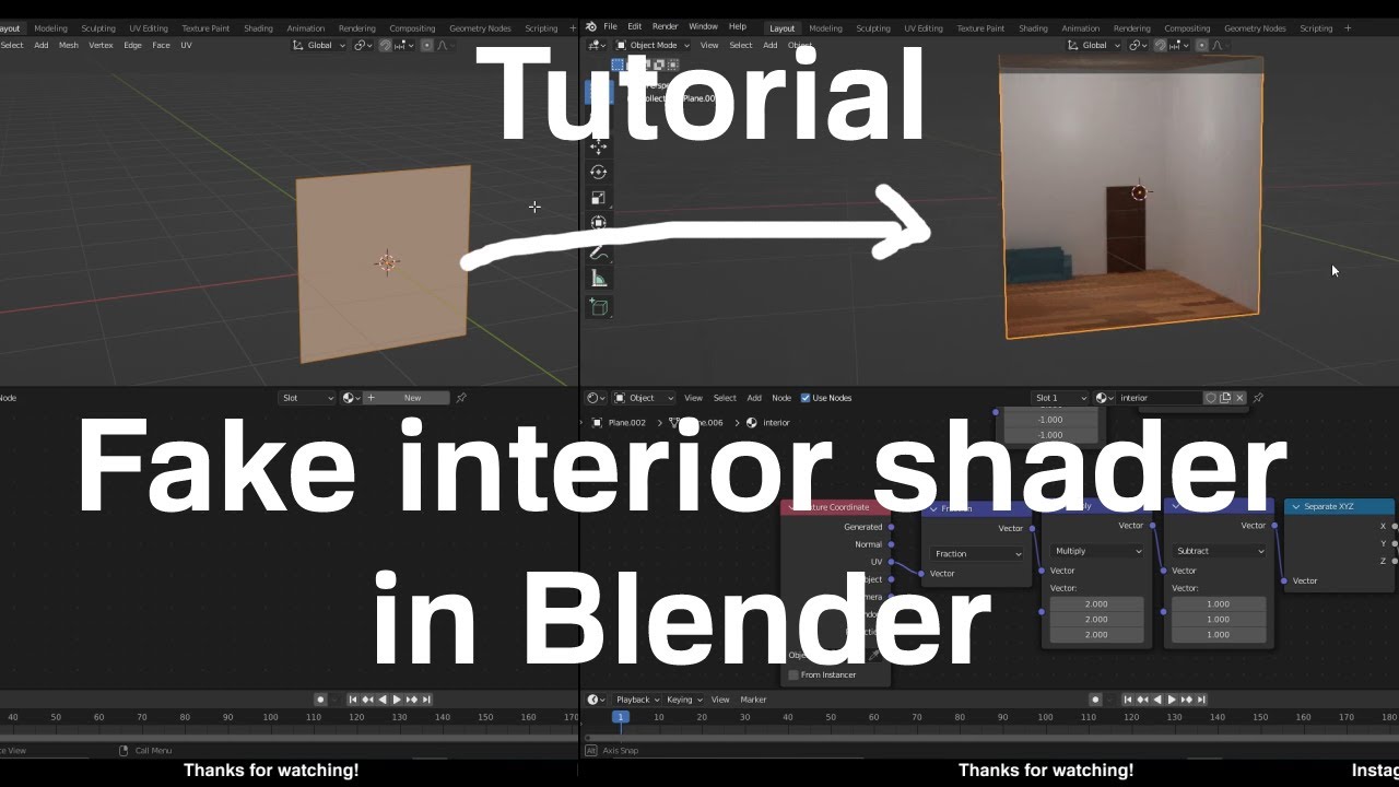
This old “Fake Interior” Parallax video brought my mind to it:
It only shows on the Negative Y so I was tinkering. Turning the effect around to +Y Normal, was easy enough but showing it correctly on X or Z was my goal so I was sniffing around the INCOMING attribute.
I’m 35% Blender savvy - I’m proud to have two or three helpful videos out of dozens of tries - and was hoping to update this technique for 4.2 but I think that will be someone else’s success story! (I did sneak a peak at your edit!) ![]() I’m just drunk with power as the thread author.
I’m just drunk with power as the thread author.
I can’t call this solved but it’s something. I don’t know what to call it.
Have you tried using the angle in the Vector rotation node to rotate the texture?
I could try - something also odd: I have to use Generated instead of the prescribed UV input at the very start. Using UV worked for me until the INCOMING row Subtracts Multiply from Absolute (three and four nodes from Geometry > Incoming
The whole thing is fishy but I was asking the original question to begin trying to straighten out my understanding.
Indeed, I followed the tut and it was not working properly either.
There are some things that bother me about the setup, the fraction node does not seem to do anything and why multiply the vector by 1 before the vector rotate at the end (anything multiplied by one is itself)? So I got rid of both those nodes (no change but cleaner)
For the UV cords to work set the first multiply node after incoming to -1, 1, 1 (not sure why he does -1-1-1)
Changing the angle in the vector rotate node from 90º to 270º (or-90) on its own did flip the hdir to be visible on the opposite face but I also had to set the empty Y in the combine XYZ to -1 instead of 1 to get the perspective back.
(I see you did that already in your setup so maybe for your viewing angle you need to change from -1 to 1).
To make the hdri he mentions scaling the objects in the room, I had to make them thinner on the Y axis to avoid distortion, the mapping is not great especially in the corners because equirectangular images are not “cubic” they are spherical……There is a reason he only put furniture at the back against the wall.
I found it much better to set the camera back to the “open wall” (not in the center of the cube) and extend the walls back. There is probably a “sweet spot” for camera placing and the rooms y size, I did not investigate it too much. I also had to squash the floor tiles on the y axis.
All in all making the hdri scaling is fiddly and what I did to avoid distortion may also change the perspective effect.
Here is the file I did with the modifications in the shader noted and the file of the room I did.
PARALLAXROOM.blend (444.9 KB)
Room.blend (133.1 KB)
It is quite a fun shader to play around with.
![]()
But now we have portals it might be easier to do a portal to the inside of a sphere with the hdri mapped to the sphere. (will give it a go) ![]()
Edit;
a shout out HelloHiHola
I realized that in my file the room was turning in a mirrored direction and have changed a few things! (sort of reversing all the previous changes, set to 90º not -90, the UV thing -1,1,1 and The Y depth 1.9 (it does make the room a bit more deep - not square.
I have updated the paralax file and explanation.
All in all I think this is highly view dependent so it is not that simple to flip things without changing various parameters.
Also the big drawback is that you have to make the room with squashed proportions when you make the equirectangular image - a bit of trial and error.


