I have a round disc with a hole in it with height ~0.5. The outside resolution is 64 faces.
I am using a modulo to extrude some face-groups to the outside. I am using a scaling to “thin out” the extrusion at the end. (It will become a gear)
In each extrusion step I use a scaling to make the scaling iteratively reach its destination at the outside. (0.2)
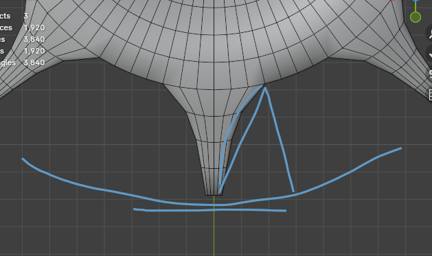
My problem is, that when I extrude/scale in multiple steps (4 here), my resulting side of the extrusion becomes curved.
My approaches:
Try to get a scope ratio for each extrusion to get a scaling-factor from that.
Do I need a angular calculation of some values to compensate the curve?
(I am using also a scale normal to 0, to make the endings of the teeth flat instead of curved, as you can see in the image. => This might also cause some distortions)
Hum, first off, if you are going for a straight line, why do you need extra subdivisions ?
Can’t you just extrude once ?
As for if you really want to keep the subdivs… it seems tricky…
Maybe you can start by trying to flatten from the start, it might be the curvature that cause issues…
Another solution would have been to rotate the side with the base as a pivot point, but this sounds tricky too…
Finally, keep in mind that gears have repeating patterns, so you might try to start with one section and finish with a radial array. That way it might be simpler to create the base shape , but that doesn’t sound easy either…
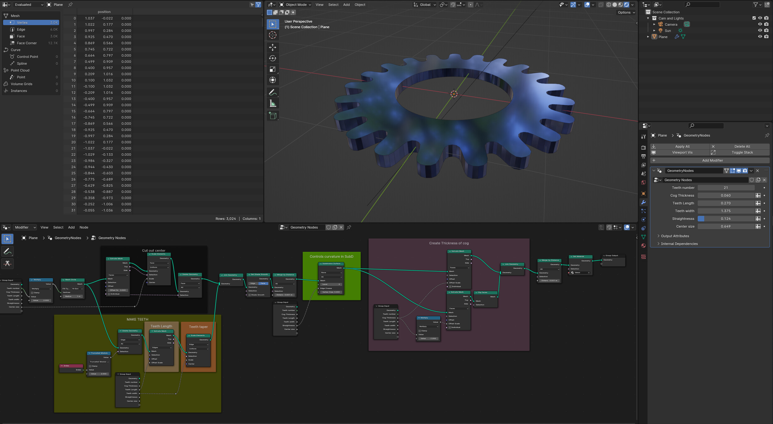
There may be some explicit reason why you need to construct your cog the way you are trying, in which case this post is not relevant, but as an alternative this is how you could create a basic cog with a GN:
There are several ways to go about this, the most obvious being to extrude the alternate edges of a cylinder. But this has restricions in how the teeth can be ‘curved’ with a SubD.
As the number of teeth is usually the base requirement for a cog, it is this which drives the number of faces of the base circle - ie it has twice the number, so alternate edges can be teeth. This also means it’s easy to have an odd number of teeth.
The above solution takes a mesh circle, extracts the alternate edges, extrudes them and then rejoins them with the original mesh circle [ which has had it’s center inset/deleted to create the hole ] . This is then merged to weld the teeth to the base circle and a SubD can then affect just the teeth. To add thickness to the mesh it is extruded twice, once in the positive Z direction, the other negative Z ( or you won’t get back faces ) then those two meshes are joined and merged. Finally a material is added.
The inputs for this cog’s variables are part of the panel in the modifier tab to make changing things easier.
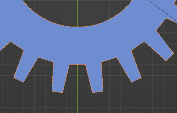
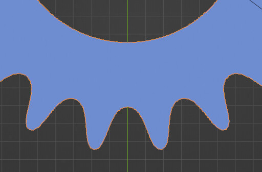
The teeth curviness can be changed with the ‘straightness’ slider:
There are definately other, more technically accurate, ways to do this, but I hope this is of some help. If you want more details on this method let me know.
A nice approach. I am using my workflow to have a height scaling of different rings. The gear ring is greater than the end of the teeth and the inside ring.