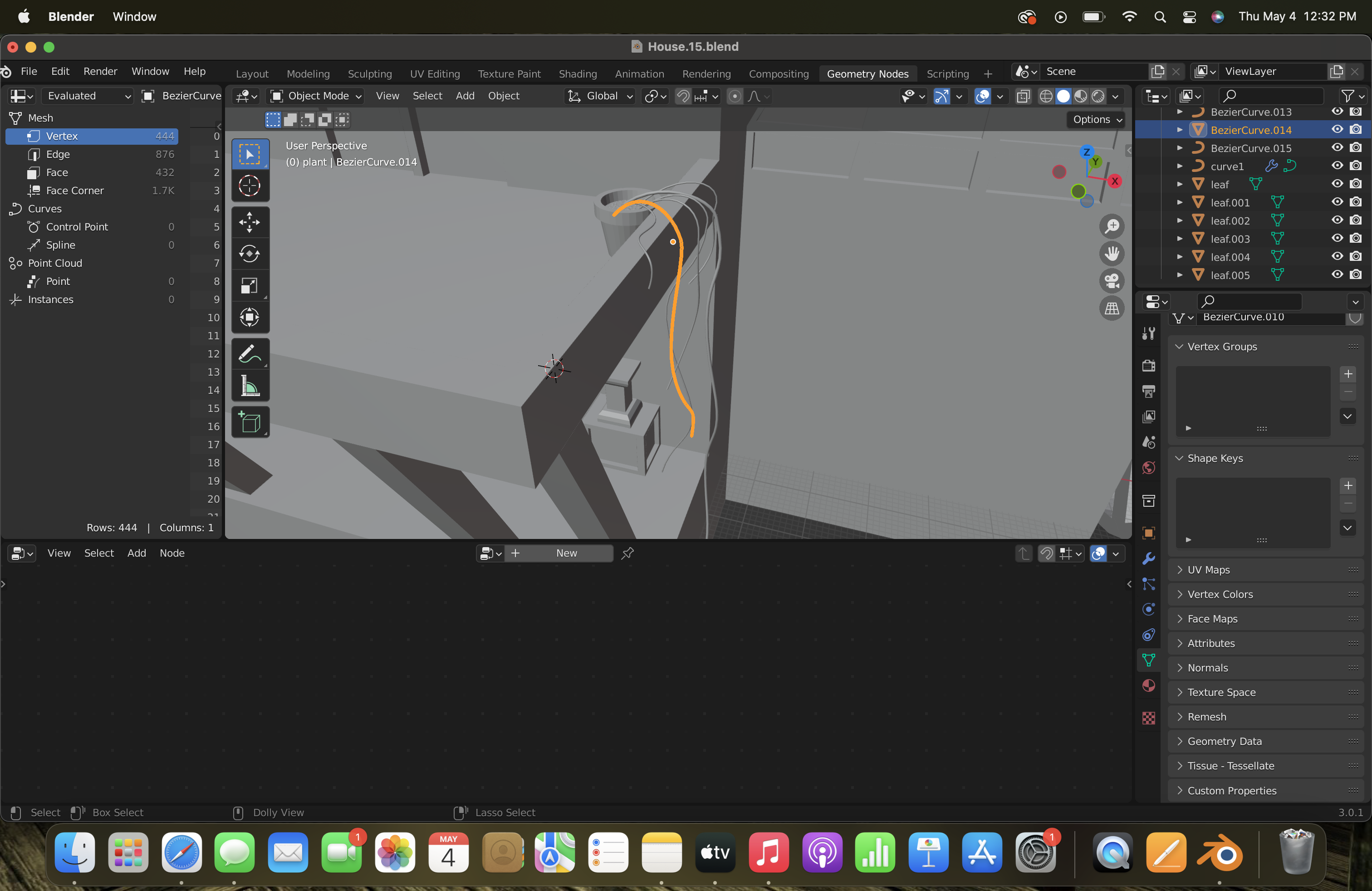
I could’ve sworn there was a support section for geometry nodes but apparently there isn’t lol. I’m trying to make a string of hearts plant. I’ve modeled a leaf and made a curve, and I want to array the leaf on the curve. I thought I found a tutorial that would help me, but when I add the leaf object to the instance, it makes the leaves huge and stacks them on each other. What am I missing?
Here is the curve I’m trying to add the leaves to. I have a curve converted into a mesh, and a duplicate curve right under it. The picture before was me trying to add the leaf to the curve, not the mesh.
First, always make sure that both the curves/meshes and the leaves have scale=(1,1,1). Un-applied non-uniform scale is cause of such issues in most cases.
[Object > Apply > Scale or Ctrl + A > Scale]
4 Likes
Use the Geometry Nodes tag (I’ve added it for you).
What tutorial are you following? Seems pretty incomplete…
Quite a lot… Something more complete would look something like this:
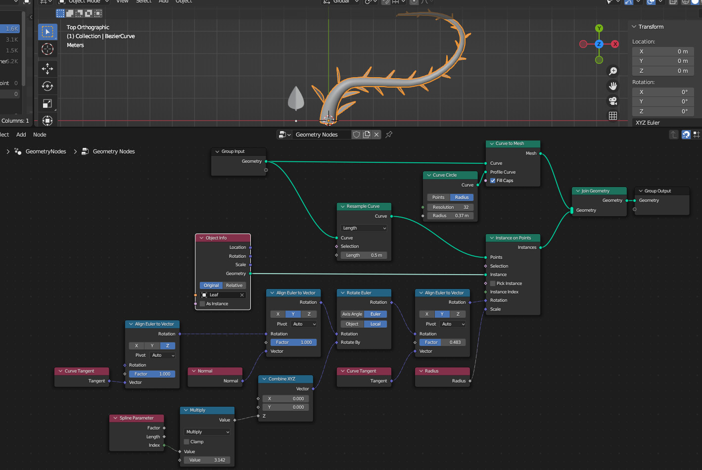
This uses the Bezier Curve’s Radius (
alt-s in Edit Mode)
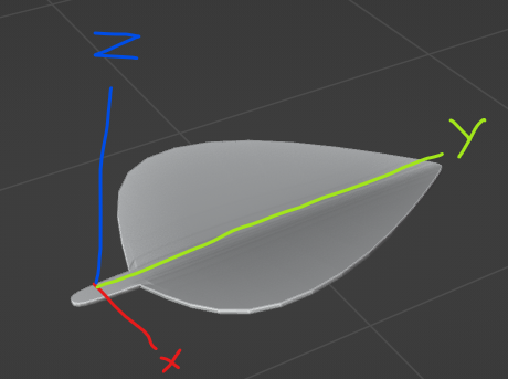
Note that the source leaf’s relative origin is at 0 Y and the stem starts at around ~0.4 Y. This is important to utilize the Radius for scaling in the network above (to match the radius of the Profile circle).
Orientation is important - the sequence is as follows:
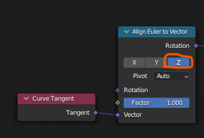
- Align leaf Z to Cure Tangent - i.e. face the leaf “up” along the curve
- Align leaf Y to Curve Normal - i.e. face the leaf tip “outward” form the curve.
- Rotate the leaf on the Z-axis locally by a half-turn per leaf (
index*pi) - Align leaf Y to Curve Tangent by ~50% - i.e. orientate the leaf tip so it partially “hugs” the curve.
Advice above about normalized scale is also important.
Good luck.
7 Likes
You have two different leaves? Leaf Z and Leaf Y? I’m confused.
I decided to use a particle system instead. Geometry nodes confuse me ![]() Feel free to explain further if want, but you don’t have to. Thanks for the answers though! I still learned something new
Feel free to explain further if want, but you don’t have to. Thanks for the answers though! I still learned something new ![]()
Looks like he means Align Leaf Z Axis…
And Y Axis.
like this…
Nonono. Don’t give up. “You can do that with geo nodes!” is the new “You can do that with Blender!” after all.
Here’s one without the pesky euler thing -
2 Likes
Nope, it’s just the coordinate frame:
The leaf’s Z refers to the “face” direction, and the leaf’s Y refers to it’s “tip” direction.
You need to understand that so you can understand how orientation works:
…i.e. the above means “orientate the leaf so the leaf face (the Z) points toward the curve tangent”.
You can break the problem up into parts and test each part individually then combine them.
Good luck.
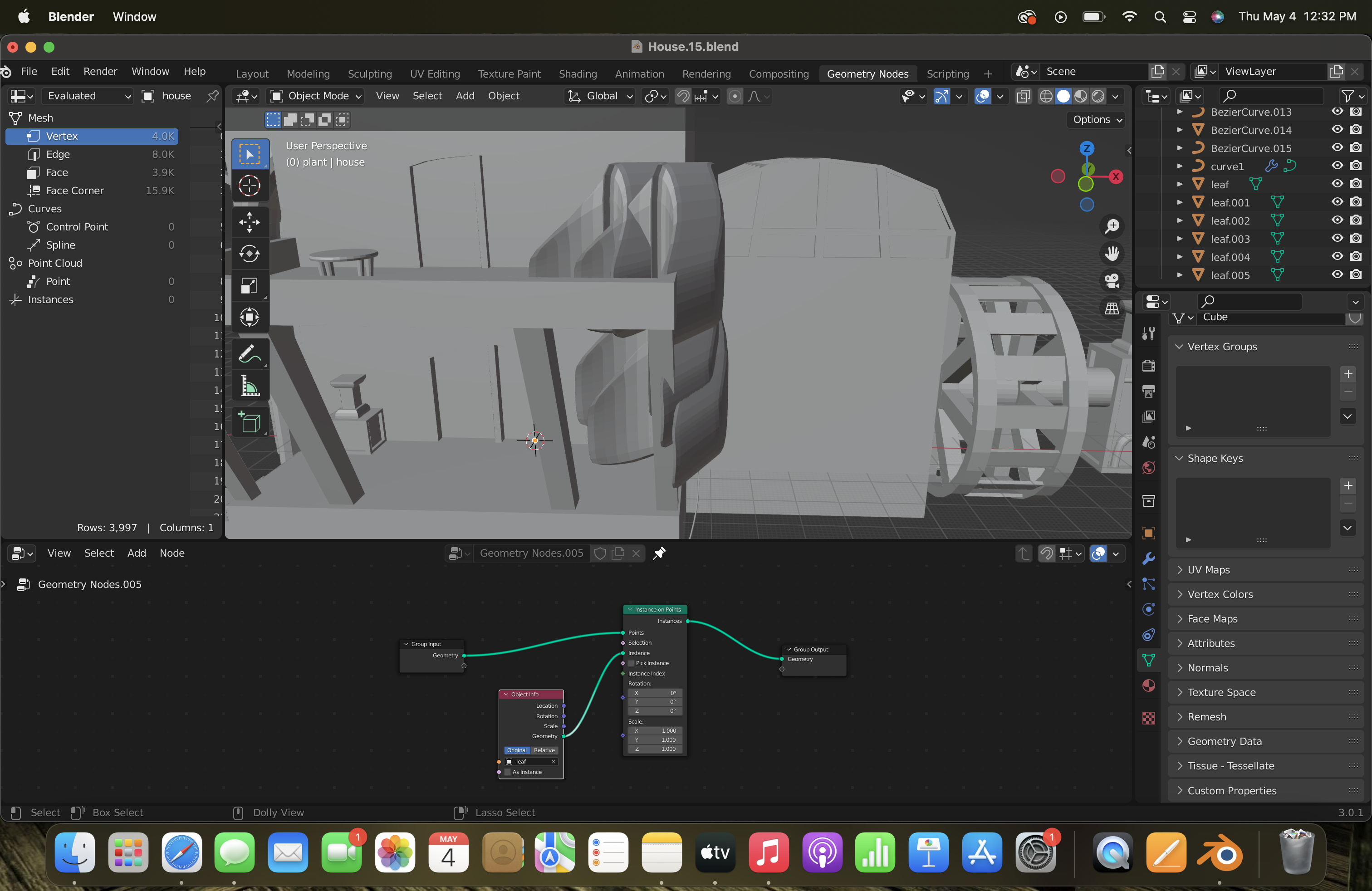
Ok I came back! I tried your method, but I’m still having problems. 1) why are there multiple leaves stacked on top of each other? 2) The vine/stem that was the curve disappeared. What now?
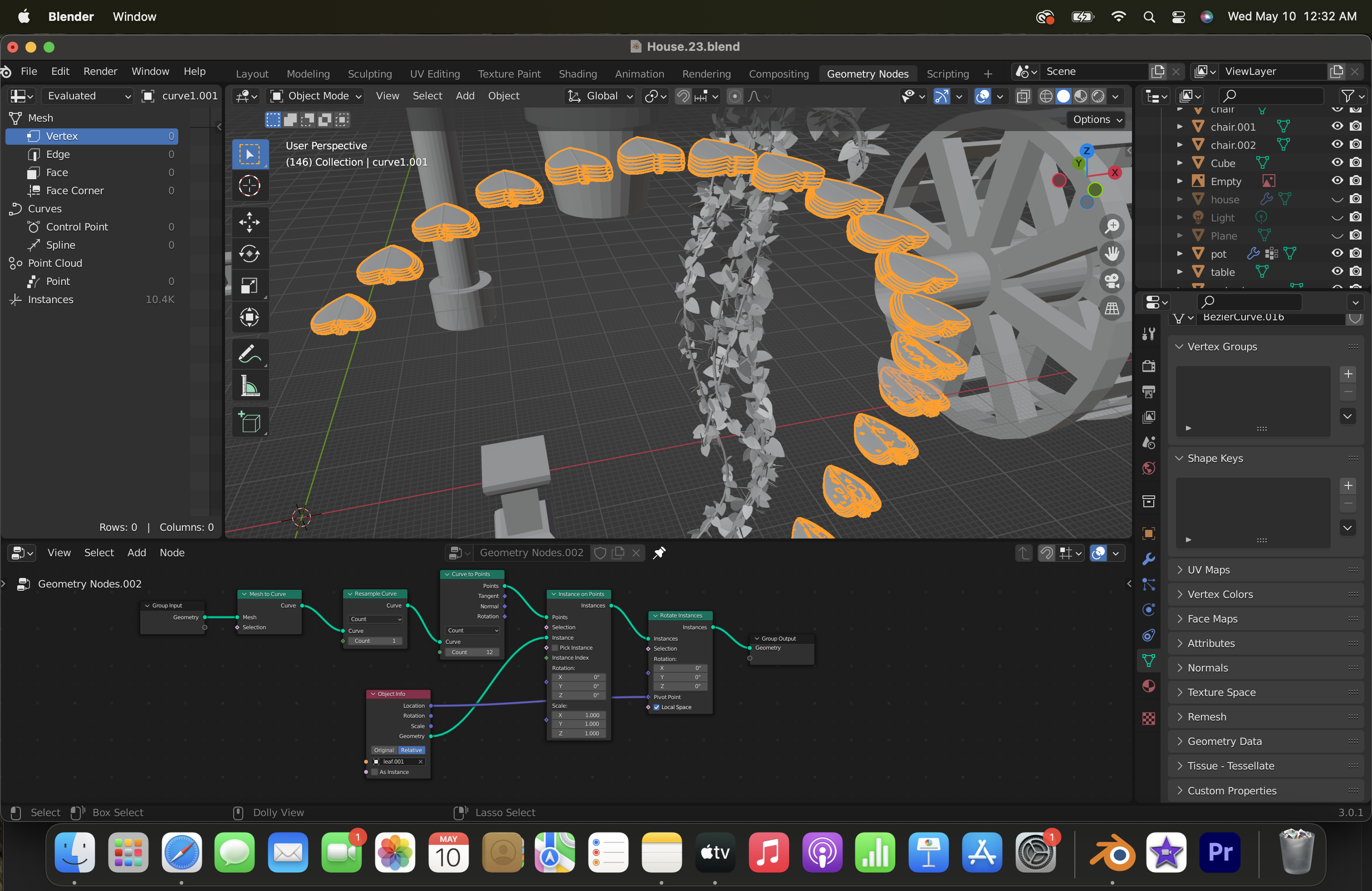
Looks like you’re beveling your curve which makes it a mesh and not a curve… disable the bevel - do it in GN with Curve to Mesh, like in my example.
Your original mesh probably wasn’t a single line, but something with thickness, that’s probably why there are more leaves instead of one at a time. Try adding a merge by distance node on the front end.

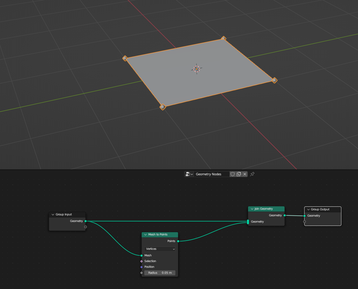
The original curve disappears because you’re converting it to points and putting leaves on it. To solve that, just add a join geo node in the end, and pipe in the front end into that as well as the second to last node, kind of like so -