They incorrectly assume that every mesh needs rebuilt, we can add a new node set, create bvhtree, cache bvhtree, and have bvhtree input for raycast, and allow the user to decide what to cache and when.
Or we can rewrite the depsgraph to do it for us, but I bet that could add some overhead.
It’s kind of a corner case (only certain nodes internally use these accelleration structures).
Reusing those structures is even more of a corner case, because its only relevant if you deal with something dynamic (e.g. Simulation Zone).
There is a lot of work to be done in numerous areas, before we can make sensible Houdini-comparisons (and you know it).
Making it work the way it does now means at least the static case is catered for and improvements tailored to the dynamic case will probably be introduced later.
… with a noticable increase in complexity, both for the user needing to string BVH cache nodes together, and for the devs as they need to add code to handle exogenous BVH structures in each node that can use one.
Particularly when your main use case is one that is explicitly not supported by the Blender Foundation. Valiant though the UPBGE team’s efforts are, realtime game engine is not a performance target by the BF.
Virtual set extensions are used extensively, (avatar, mandalorian, etc)
Upbge fork has a script to record gameplay as fcurves, and render offline, but it’s not needed, a modal and/or* blender sim nodes could do, if they were optimized.
I would rather we not need upbge fork at all to do this stuff. record.blend (850.9 KB)
Last I checked your game project requires support for a large, dynamic, environment. I do not think Fcurves to record node output is going to allow for anything other than cutscenes or other very specific cases.
It gets even more difficult when you realize that Geometry Nodes running at 60 FPS is not enough. Unless the UPBGE team rolled their own version of Geometry Nodes for game then they are dependent on the idea that the BF will have them running fast enough to allow for 60 FPS after game logic and physics are taken into account (and BGE Python was never exactly a speed demon).
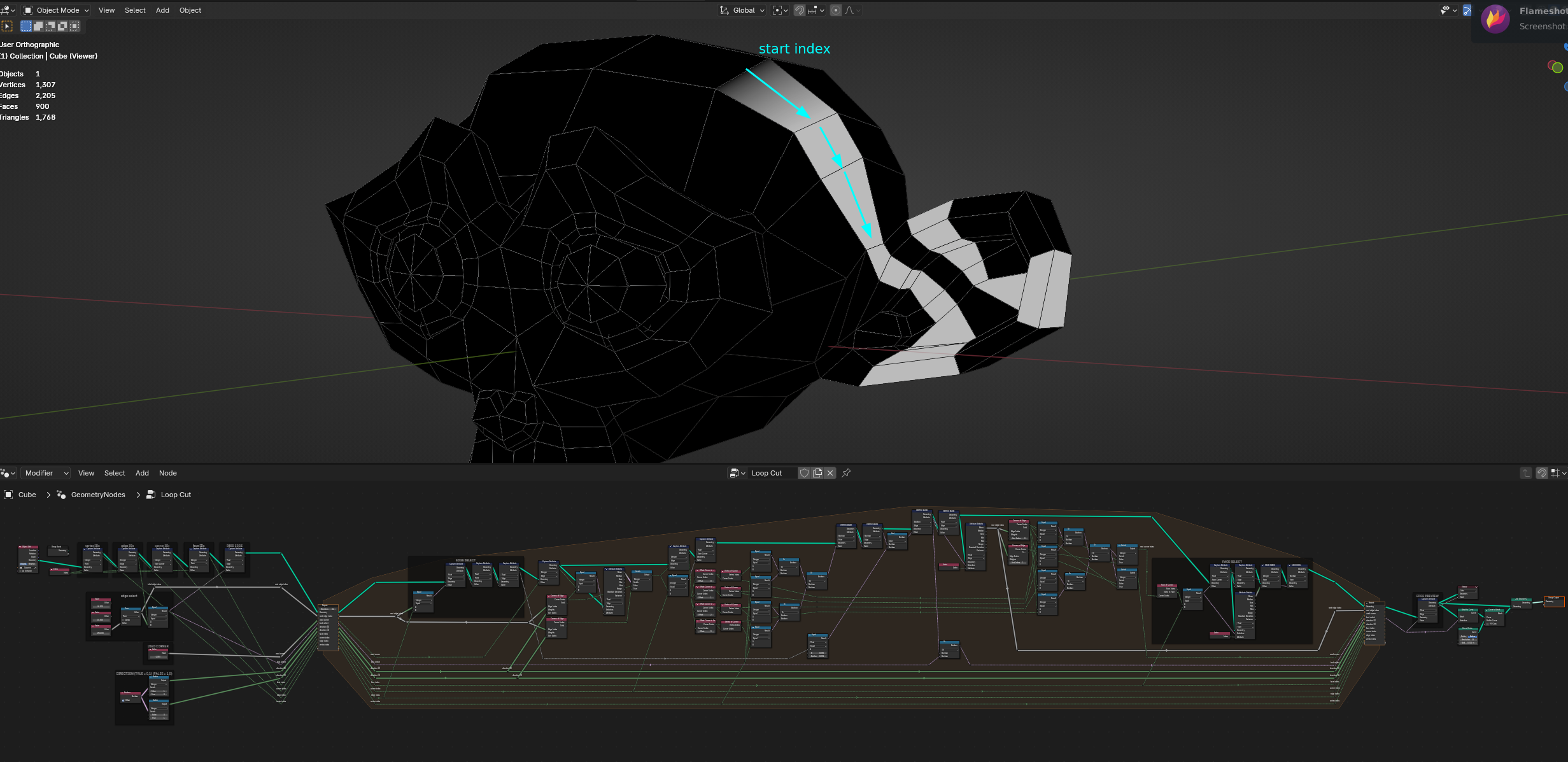
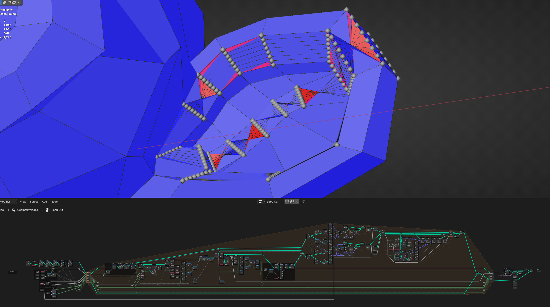
For the past couple days I’ve been working on Loop Cut node group. It’s still WIP, but we have some breakthrough with edge ring selection.
The hardest part was cross-checking face corner selection. Bmesh is very chaotic and basically all naive approaches failed miserably. This is 6th iteration.
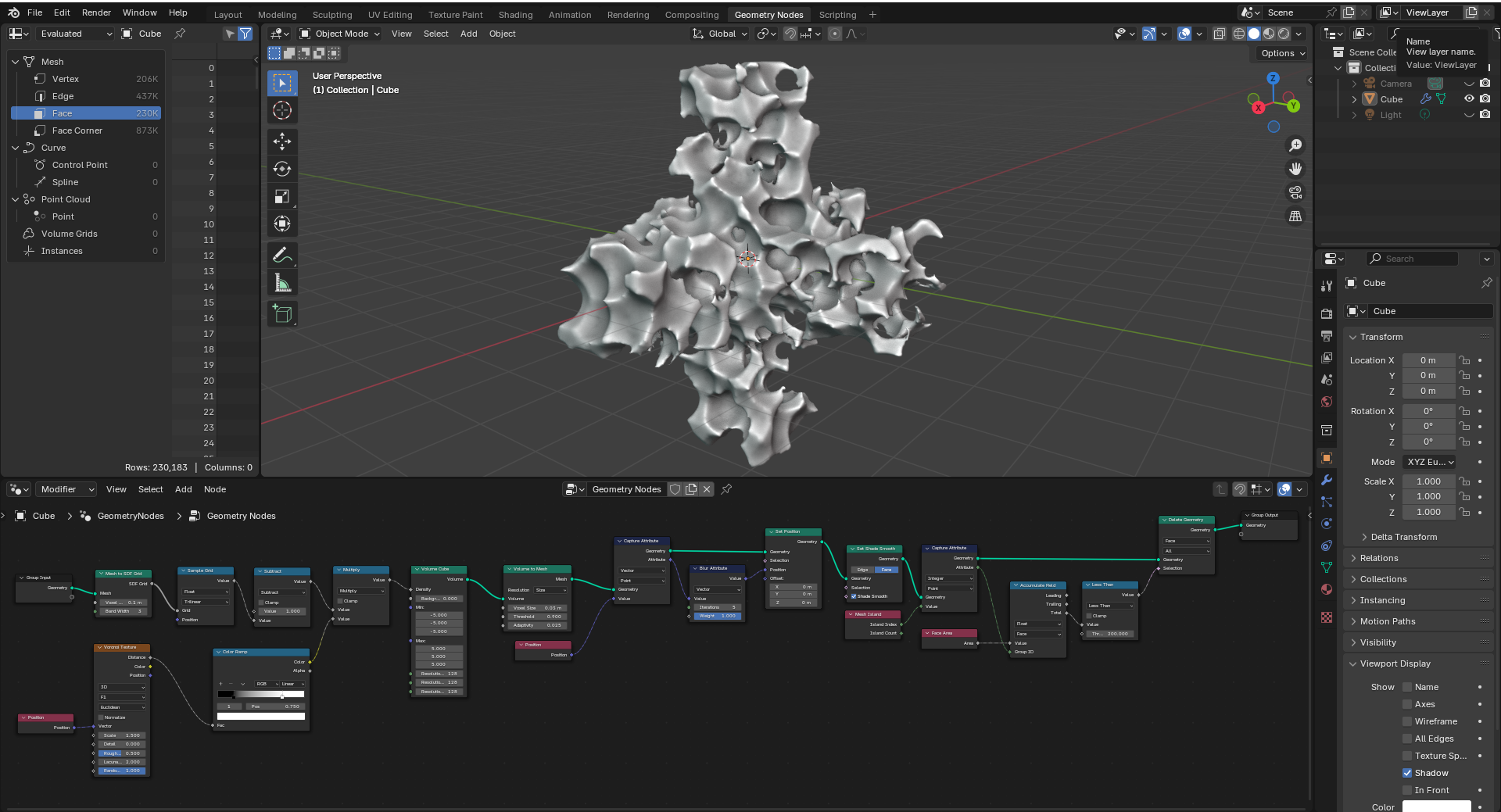
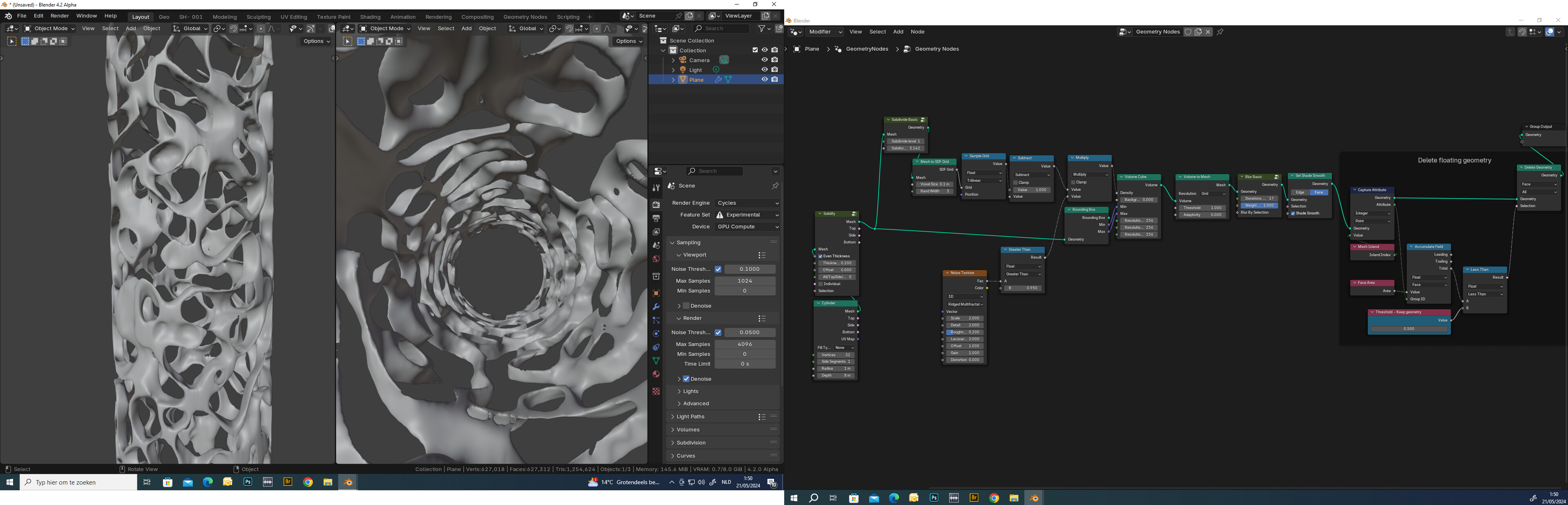
The new SDF nodes, especially when combined with a technique to trim off small mesh islands that might result from it, allows for the creation of extremely complex meshes for objects like sponges and coral (which would be terribly slow and difficult to make using standard modeling tools or boolean operations).
But right now we don’t have it, so I took the matter in my own hands. Its an interesting challenge to do with existing nodes only - full loop cut I mean, not only edge ring selection.
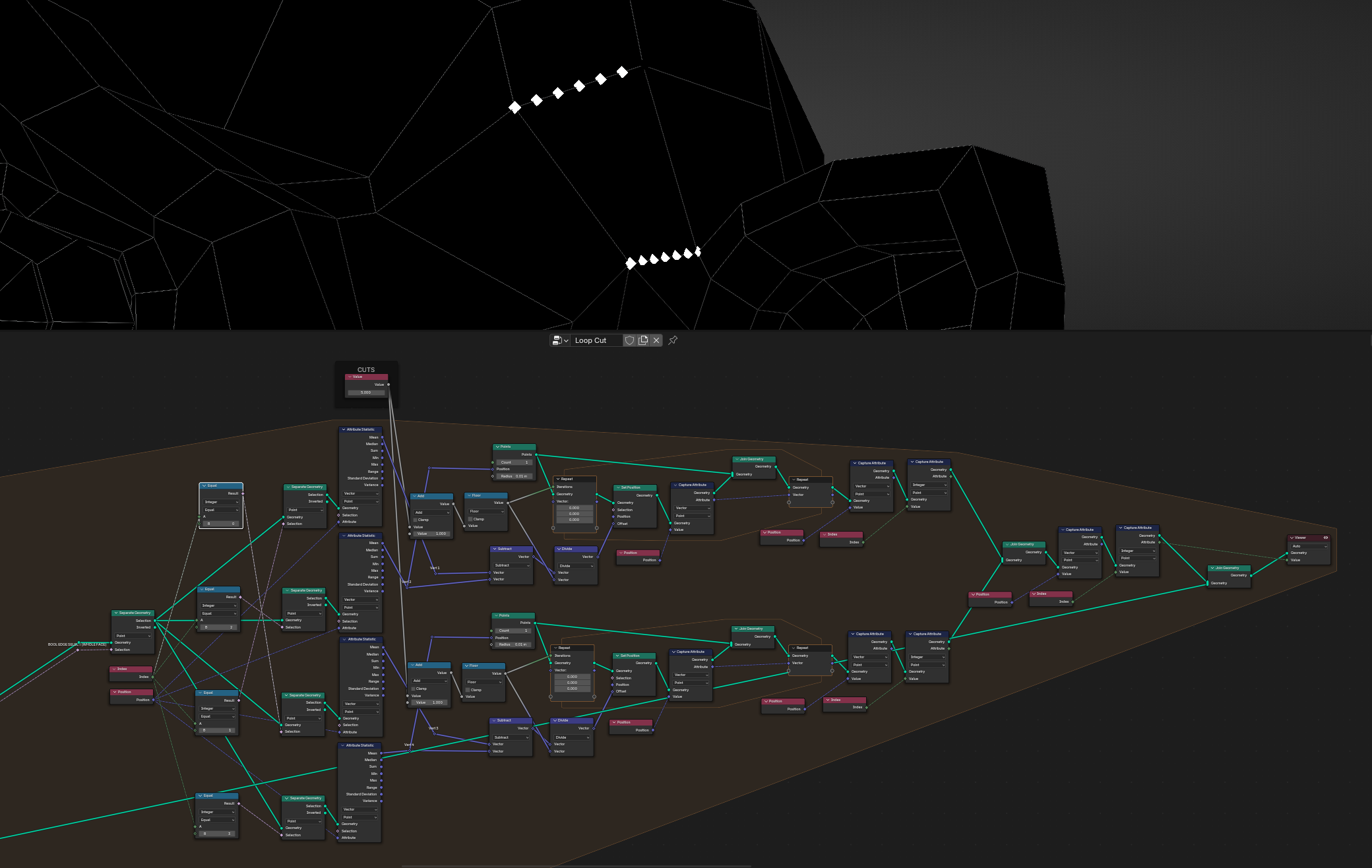
It’s still WIP, and I hit a wall with distributing grid primitives. It will take some time to find the solution for this. I might redo the whole group again.
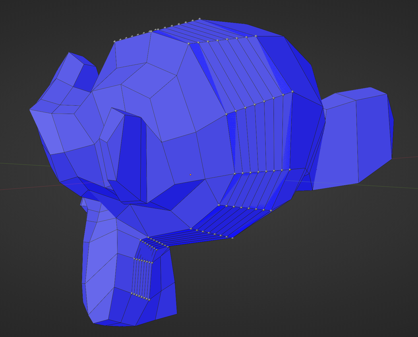
The goal is feature parity with ‘loopcut and slide’ operator + having partial loops.
Biggest challenge that I can see right now will be to detecting when loop cut path cross itself and handle the crossing.
But first I want to test edge ring build Illya provided.
There is not a lot of mesh modification in the screenshot. Its mostly operations on mesh attributes like index, position or boolean selection. Loop cuts you see above are done with generating N number of the most basic grids (planes) per every face in the edge ring. Rinse and repeat.
The problems start with using mesh (vertex, edge, corner and face) indices as they are not stored in the same order in every face, so there is a lot of attribute conversion and storing.
Alright, so you place subdivided grids, align them with existing faces? then? delete original faces, join new ones, merge by distance? that’s a whole factory
Its a little convoluted, especially selecting next parallel edge part.
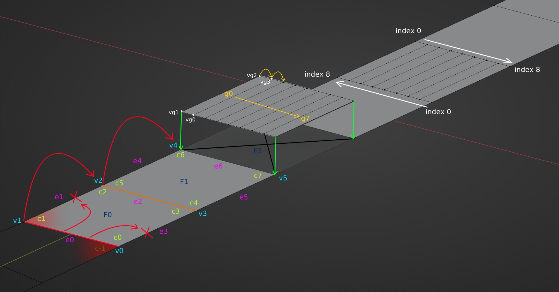
I didn’t follow the code implementation as Geometry Nodes do not have for and while loops. Parts of the logic that I’ve made are workarounds for infinity loops like e0 → e2 → e0.
For selected edge e0 pick one corner (c-1 or c1). This sets the selection direction.
Through attribute and domain switching for face F0 exclude e0, e1 and e3. Pass the remaining edge as future selection. Edge e2 will serve as a base for finding e6.
Along the way store the positions of vertices (v0 → v3).
For edge v0-v1 distribute N number of points, and same for edge v2-v3 (marked white).
For edges e0 and e2 find two lowest vg vertex indices and generate a face based on those 4 vertices (marked yellow g0 - g7). Move 1 index up, and repeat.
The main problem right now is that vg indices are not starting from the same side. This is marked with white arrows.
I haven’t got to removing original faces yet - but it is shown here with F3.
Another problem I can see is that after merging there will be hole in the mesh between vertices v4, v5 and vg verts from generated mesh. Solving this wont be easy, but it is 100% doable. We have all necessary selections for it.