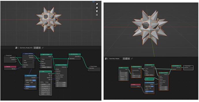
Thanks for the help. However, @Hadriscus solution is exactly what I needed!
Oh if only, man… I am in awe everyday at the stuff in this thread, so whatever I can give back
Cheers
what @Astronet said. I am still trying to grasp the difference between transfer and capture attribute. that was a great example file to analyze. I am getting closer 
Hello!
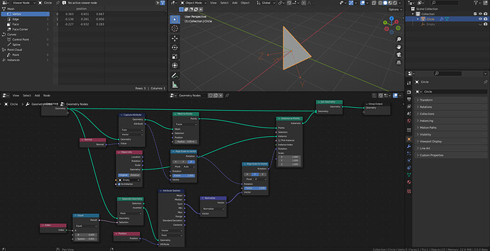
I want recreate Instancing Faces in Blender 3 Geometry Node.
But I ran into a problem. Instanced object not aligned triangle normal. Rotation weird.
Here is what i want:
My geometry node:
Can you help me?
You need to create additional vector by subtracting 2 vertices position from each other.
A hacky way doing this is by getting 2 vertices with separate node and with a attribute statistic node getting vector
I am not sure how to do it in easy way, when you want to align it to multiple faces
2021-11-13 11-30-34|video
Live updating model and measurements based off of user chosen input parameters!
EDIT: here’s a youtube link so you don’t have to download it https://youtu.be/j1cSD6OhgIo
I’m confused. What do you need the Transfer Attribute and Align Euler to Vector nodes for?
Thank you for your help. Unfortunately, I would like to align it to multiple faces later. But as I see it, it’s quite complicated to solve.
Anybody got a solution for this problem?
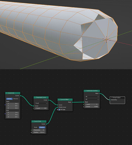
Subd Node gives me a weird result at the start point of the curve.
In the latest 3.1.0 alpha, the points are welded correctly, but the cap has a star shaped shading artifact that will only vanish if you apply the modifier.
So You re saying this behavior is a bug and it cant be corrected at this time?
The unconnected faces seem to be a fixed bug - you can just get a recent experimental build and try it out. The shading is not perfectly smooth because the edges between cylinder and cap are marked sharp, no idea if it is already possible to remove this from within geometry nodes.
How can I instance an object only at the end point of a curve?
The curve points Z positions are being animated by a Noise texture.
A copy of the curve has its length animated via the Trim Curve node.
I want a single icosphere that follows the end point of the trimmed curve.
Two options:
- Make the end factor of the trim curve node 0, animate the start instead, that will get you a single point spline.
- Use the Endpoint Selection node, which is designed for this purpose.
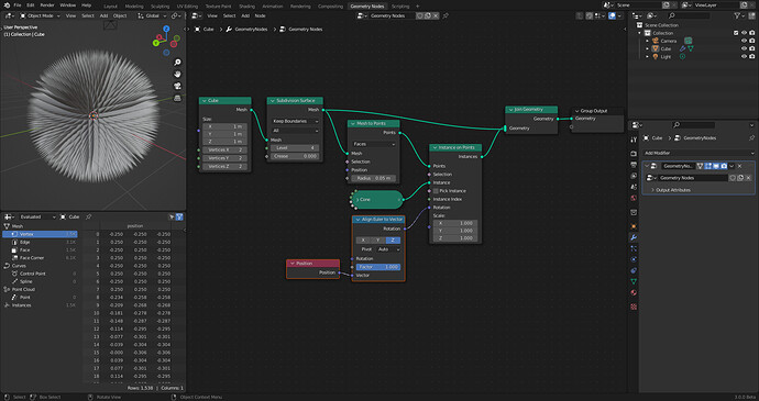
I am trying to put the Cone mesh object on the faces of a cube with subsurface modifier. I get the cones to line up on the faces. I have not been able to get them to rotate so the bottoms are flush with the faces.
Here is the screenshot of my setup.
I would appreciate any help with getting the cones flush with the faces.
You need to capture the attribute from your initial geometry (before mesh to points), otherwise it’s just points and they have no normal. You can check for this in the spreadsheet editor. There should be no need for transfer attribute either. You’re trying to create a vector from face centers to edge centers… I’m not sure why ? you can just use the normal attribute.
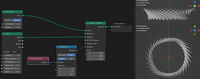
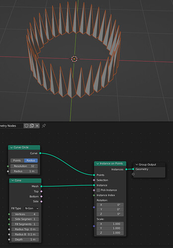
Struggling with aligning instances to the shape of the curve, nothing seems to work.
The instances are not supposed to stick out of the XY-plane.
Anyone knows what am I doing wrong?
Shout out to Drachenstrum and Hadriscus for helping me with getting the cones to sit on the faces of a cube. They are both great solutions. Drachenstrum yours allows for more dynamic creation if I want to add more faces is it simple. Hadriscus I love yours because It used my original cube. I can use it for different types of scenes.
Here are both solutions side by side. Again, thank you both for your help; both of your solutions are much more simple than my original attempt. I am learning so much from this board. Thanks to everyone out there.
