With the Sample Curve node, one can do a lot of crazy awesome stuff. However, it’s somewhat limited since the only set of outputs from the node is position, normal, and tangent. Is there a reason why an attribute like radius isn’t also part of that output?
Here’s a typical scenario: Imagine I have a set of points distributed along a spline. With the Sample Curve node, I can pretty much “slide” these points along the spline. If I also wanted to displace the points away from the curve (along its tangent) based on its radius then that becomes tricky because there’s no way to “sample” the radius along the spline. Maybe there’s another way of doing this I’m not aware of? (if there is can someone please describe it? thanks) If for example the spline above is converted to a mesh then what I just described would ensure that the points always remain on the surface of the generated mesh.
Actually, a more robust solution would be to have the sample curve node behave like the transfer attribute node where we can connect an arbitrary attribute we intend to “sample” from the curve and then get just that as the output.
Is something like this also planned for the sample curve node? @HooglyBoogly (sorry I’m not sure I’m supposed to tag you to these questions. I imagine devs have their hands very much occupied at this point. Just that this question is directed towards developers and so far you have really helped me with understanding how the sample curve node worked  )
)
Yeah, that’s planned, there’s a task for it here: T91650: Support sampling custom attributes in Sample Curve node.
They pass the tilt and radius along, so when I tilt a part of the curve, the extruded curve primitive rotates too. Just the same as regular curves, really! But if I don’t bring them into the GN explicitly, they’re lost
Hans, just checking that you’re aware that Material ID’s aren’t passed through GN for curves? Re: my attempt higher in the thread. It’s a real showstopper for this particular nodegroup for me, so I’m curious whether it’s on the radar at all
Ok wow! Literally every time I figured geometry nodes might be lacking or buggy, turns out the devs already thought about it months earlier and are already working on solutions. This is just amazing! 
That’s weird, the tilt and radius are always preserved for me (without explicitly bringing them into the node group). As for the materials on curves, see this discussion on devtalk
I’ll have to doublecheck that! I might just have done something wrong early on and made the wrong conclusion!
I’ll have a read through that thread too, thanks a lot.
You guys fix stuff faster than we’re able to complain. 
By the way, this is one situation where users might need to sample/capture several attributes at a time. Not that it’s very complicated to use several nodes, but : any plans to make the “capture” sockets into multi-inputs ? (or is that a UI nightmare?)
I just jump into this post regarding “realize”… If I understood correctly the realize node makes an object real and not virtual like it is in instance mode? But if you have a collection how do you realize a specific node or set of nodes from a collection? I tried but got only all realized or not… Also where do you place the realize node in the tree?
Be more innovative with your complaints then.
If you can no longer complain about the basics, then complain about how hard it is to do things like simulating a pile of sponges in a rainstorm while a man cuts them with scissors.
Okay, I don’t recommend that, but if the roadmap pans out…
I just noticed this today so I’m not sure if it has always been the case but when I connect a rotation to the group input and then set the min/max limit to some arbitrary number, blender seems to completely ignore the limit and just go on from -infinity to infinity. This only happens when the input is vector and has a rotation unit (which cannot be manually set btw like with setting the type. I wonder why). If I manually created the input and set it to vector myself (in this case there’s no unit, just a number) then the min and max work just fine.
Did I do something wrong or has it always been like this?
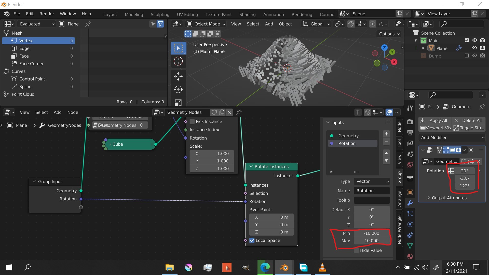
EDIT: And… just after asking this I figured it out! The min and max value need to be in radians
Haha ![]()
The challenging part in your brief is… the cutting. The rest : if geonodes can do it, so can I ! But topology-altering simulations are far away I presume. Especially cutting all through a mesh, effectively making it two independent pieces… If I were given Blender5.3.exe (in the future, executables are numbered), I’d probably go for a method involving volumes booleans, tagging the cut/subtracted surface voxels with an attribute and remeshing just that part as the scissor progresses through the object. The output would be fed into a soft body solver that’s able to hold water from a flip simulation, making the sponges swell. Then I’d add some glazing and call it a donut
classic Blender gotcha, the riggers know ![]()
@yvesbodson2 I had a go at your issue and found no way to isolate one instance from the rest. Maybe I’m just thick, because I haven’t worked with instances a lot yet, but I think we’re just lacking the tools. I tried separate geometry but that node has no option for instances (yet?).
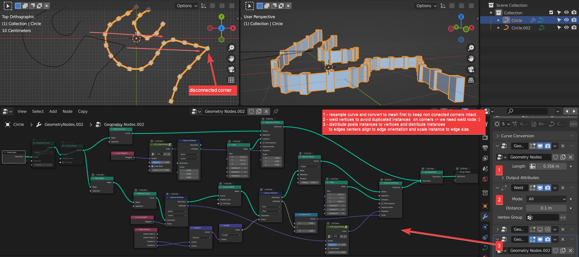
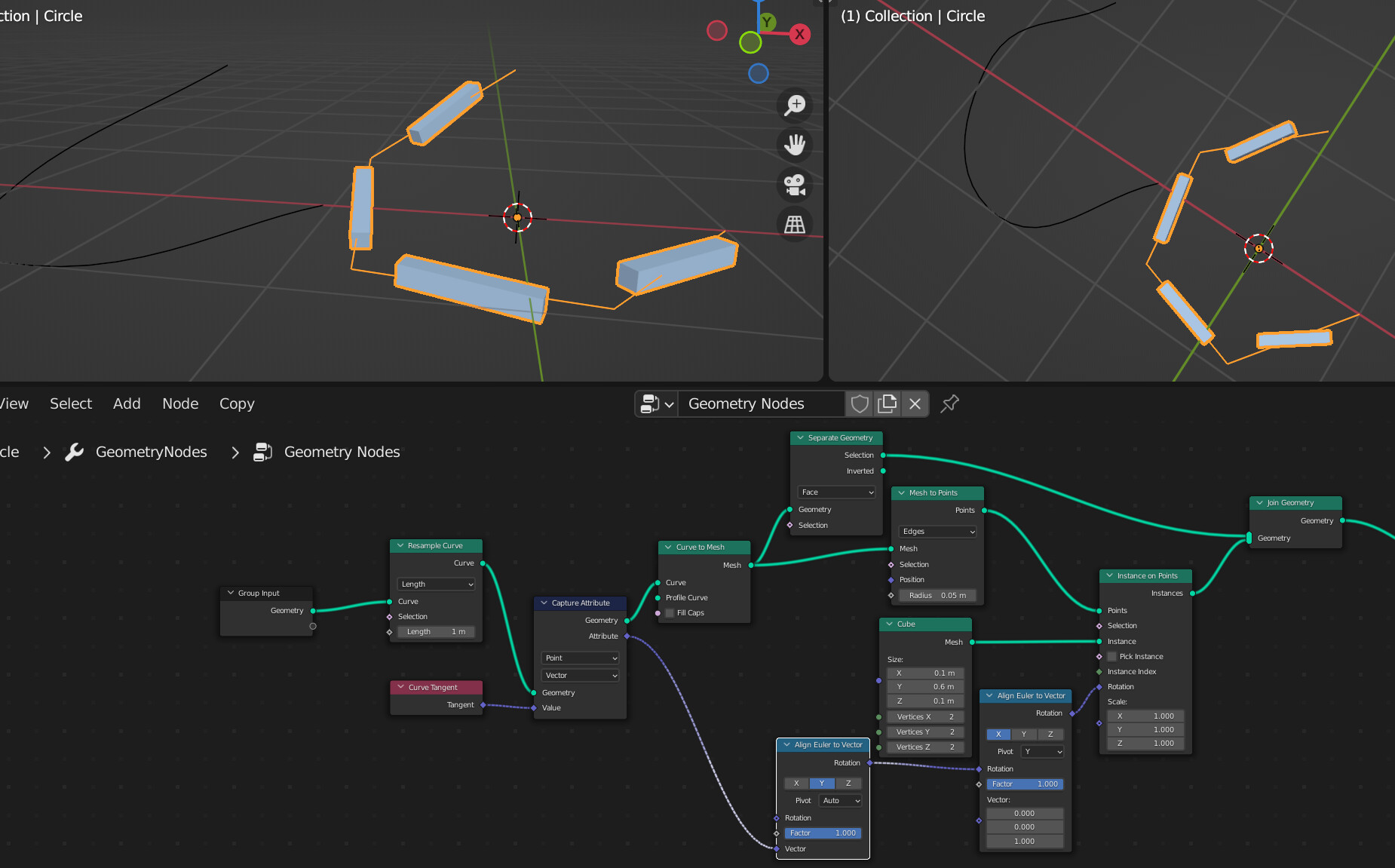
Thank you… but dont works… Im getting incorrect alignment to edges… I think tangent is from point, not segment… I need to get edge/segment aligment.
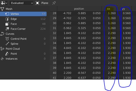
These xx and yy values came from realizing instances of a collection of objects that were generated by different geometry node trees. I would like to use these values somehow in my new, totally different tree from the one where these values were generated. So I see them in my spreadsheet but I have no idea how to use them in this tree. What If I just wanted to use the xx value in a math node for example? This seems like an elementary problem but I really have no idea how to do it. With attributes you were able to use something like attribute MAth node and just type xx, but with Fields? I have no clue. Help!
It seems like the devs. have made a very good choice by having optimization be a focus as well. Erindale continues to break records with his most recent mega-tree containing over 7000 nodes.

With procedural modeling nodes in the works, it will get to the point where a lot of scenes can be little more than piles of parametric objects (even though I myself will likely mix it with destructive methods for the foreseeable future, and not just for performance reasons).
I look at stuff like this, and I find it hard to believe we are still talking about the same app. that was once so lacking in functionality it did not even have Undo.
ironically true…
Actually, Hans already has a branch for volume based modelling/ sdf/ level sets. So, the devs are still four parallel universe ahead of our complaints ![]()
Hmm… thats weird. the attributes should be averaged between the adjacent points after the mesh to points. Anyways, for the time being use this setup
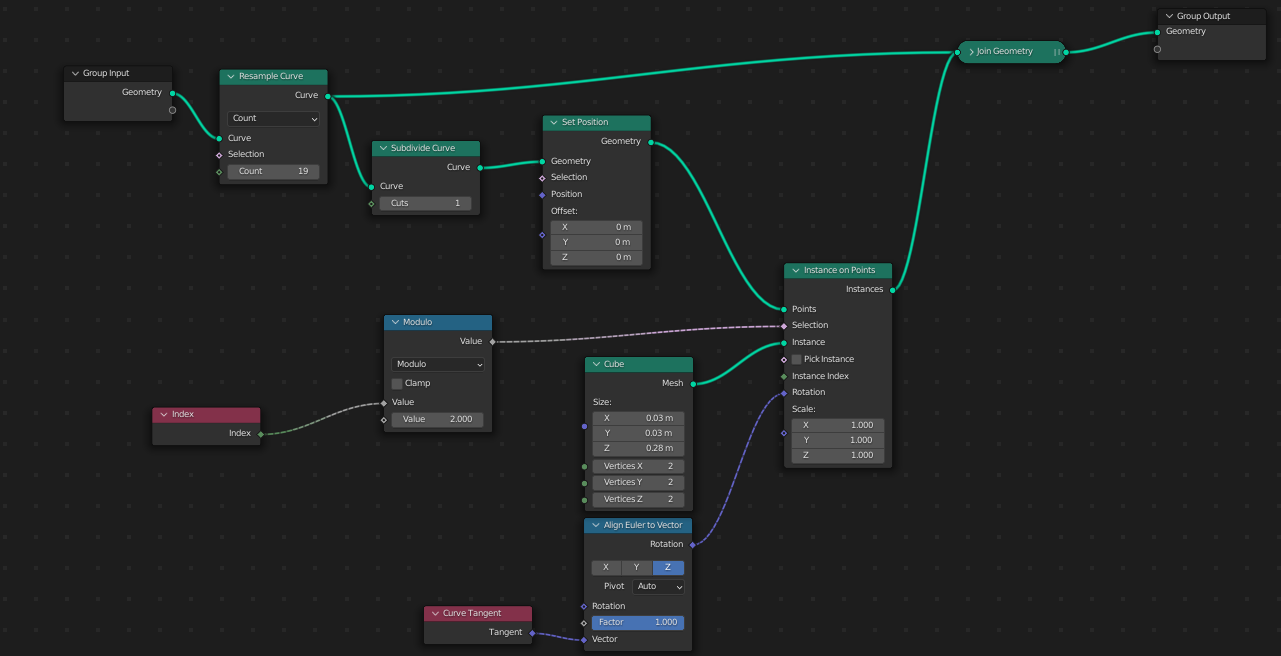
(ignore the set position)
Edit: I tried to manually average the position and tangent between adjacent points, but it is still a bit off. Maybe its more complicated than that.
Materials on Curves are spline based.
But spline index is lost by conversion into mesh and, anyways, can be different from initial material index.
We have to deal with face corners after conversion into mesh.