Geometry Nodes

Merge by Distance; Connected Mode.
rB81ec3dce6542 (blender.org)

It makes the operation much faster if you can utilize it, though this should also be useful if you need to remove nearby vertices as a cleanup operation without separate parts being welded together.

10 Likes

How can I get a texture from shader nodes to exactly match a texture from Geometry Nodes

Voronoi in Material:
image

Voronoi in Geometry Nodes:
image

image

Geometry nodes and the shader use different defaults for the coordinates of the Voronoi texture. Geometry Nodes bases them on the “Position” field, while the shader uses the “Generated” coordinates.
This is probably the case for most texture nodes, but I didn’t check this thoroughly.

Here is how you can match commonly used texture coordinates from the shader in geometry nodes:

Object Coordinates

Generated Coordinates

UV

21 Likes

Is there a way to select border edges with nodes?

3 Likes

I had been randomly trying a bunch of crap to get a value from the geometry nodes to control the scale of the voronoi in the texture and I’m certain I never would have figured out the solution in that 2nd screenshot :sob:

Is there a way to have a cube go in the direction that one of its faces are facing?

we can use a curve and sample curve to push a object along a curve / align to it easy enough @Eldyn

pushing the way it faces each frame, and ending up at a place that is deterministic is not yet part of the design without a physics engine. I have hacked particle behavior in though using upbge

each frame I take the final evaluated position of the particles and overwrite the ob.data.vertices[index].co with it

okay, thanks

you can use equations and time to change the way you sample it, to make it seem like it’s accelerating though

here is a example of a sim using geonodes + upbge**

2 Likes

This seems to work perfectly but I just can’t understand the tree. Why do you have to scale by 0.25 and why do you have to multiply 8 by the random value?

Would it be possible for you to explain all the steps?

Also a small simplification: you don’t have to capture attribute on the random value you can just use it directly.

Why do you need to subdivide the plane so much for the UV map to work with Geometry nodes?

I guess it’s because even though they are using the same coordinates, the geometry nodes version of the noise gets stored in the vertices/points, and you need more resolution in order to display vertex/point attributes and match it somehow to the shader version of the noise node. Kind of a pixel screen display, the more points the better resolution. It’s a guess though.

2 Likes

Neat, good to know. I’m sometimes a bit paranoid about capturing attributes. I don’t always find it obvious, when I can trust them to do what I want them to…

Not really sure where to start in terms of a step by step so I’ll limit myself to answer your concrete questions. I hope I can manage at least that. :slight_smile:

The 0.25

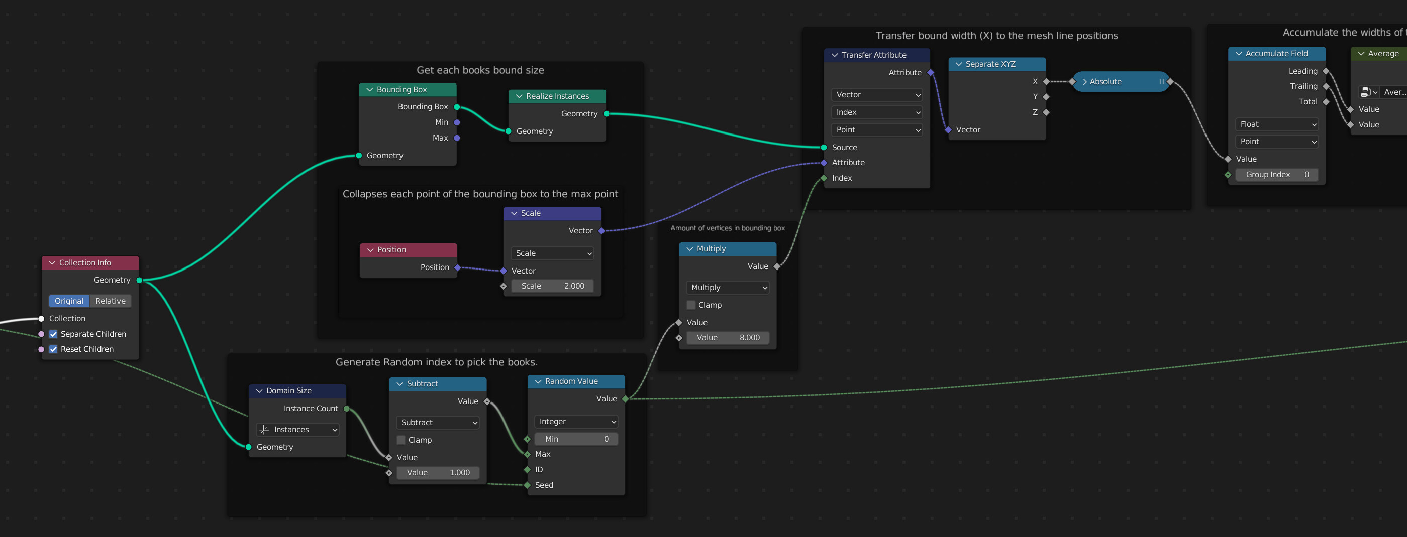
The calculation of the bounding box size is based on the assumption that the object origin of the book objects does not lie outside the objects bounds.
With that in mind, we know that two the absolute coordinates of two diagonally opposed vertices add up to the objects bound size. Since the bounding box mesh we’re accumulating the vertex positions of has 8 vertices, meaning 4 pairs of diagonally opposed vertices. So the result of the accumulate node is 4 times the size of the actual bounding box.

Multiplying the random value by 8

Our goal is to now get the bounding box size from the realized instances back to the actual book instances. The realized instances are large mesh and there is no domain that neatly translates between the mesh and the instances.
What we know is, that each point in the mesh has the size of the bounding box it belonged to properly stored (that’s what we do with the Capture Attribute* node at the end of the “Get each books bound size” frame) and we can retrieve it with the Attribute Transfer. Fortunately we know that each bounding box mesh had exactly 8 vertices. So the index 0 is referring to the first point of what used to be the first instance’s (instance index 0) bounding box, the index 8 refers to the first point of what used to be the second instance’s (instance index 1) bounding box and so on.
This only works out assuming the Realize Instances node doesn’t shuffle things around, which it doesn’t appear to do.


As you see the whole setup is quite brittle and looking back at it there are probably a few things I might do differently now:

Bounding Box Calculation

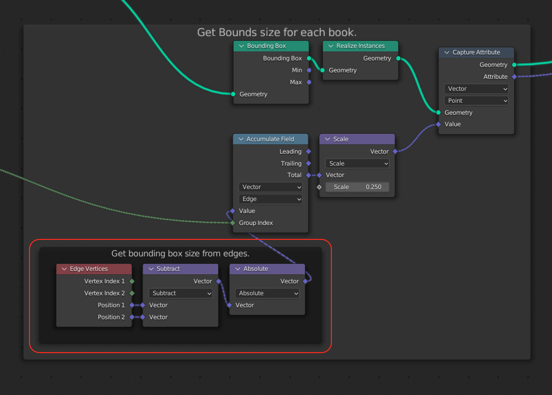
Rather than hoping that the meshes origin is within the bound, we can get the bounding box dimensions directly from it’s edges:

With this you get each edge as a vector. Because the edges come from the bounding box mesh the are nicely aligned with the x, y or z axis and we can just add them with the accumulate node. We need to use the absolute, since some edges could be oriented to point in the negative direction.
This again will give us 4 times of the actual bounding box size since the box mesh has 12 edges, with 4 each parallel to one of the axises.

Getting rid of multiplying by 8

The assumption that the realize instances node always keeps the order in tact might not hold true at some point. Or sometimes you might have to do a few more operations that change the indices.
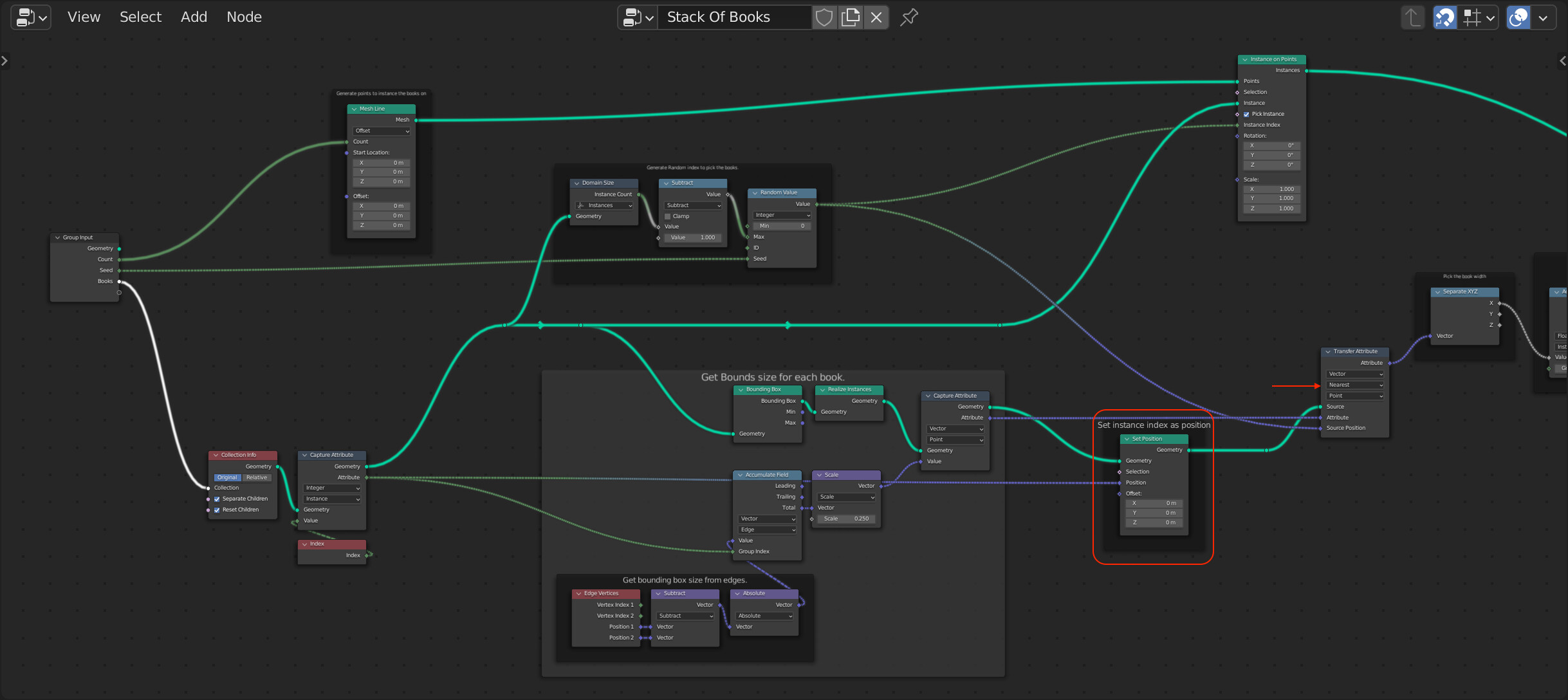
You can use the Transfer Attribute in “Nearest” mode to transfer attributes based on attributes of your choosing to make things more stable. E.g. once the points in the mesh with realized instances have the attribute with the bounding box size, their physical location is not important to us anymore. Therefore we could simply set the points position to the index and then use the random value as “Source Position” to directly get the attribute from right points.

It feels a bit hacky because you have to set the position of the points to something that doesn’t really make sense as a position, but it works.


@thinsoldier: It’s exactly how @Strangerman explained :slight_smile:

3 Likes

Hey! Thanks for the explanation. The guys at Erindale’s Discord and me found out you can simplify your tree a lot. You don’t actually need any capture attributes.

Your solution with the Edge Vertices is very interesting, I’ll have to look into that deeper. It’s definitely an advantage not needing the origin within the bounds of the object.

In any case I have to thank you a lot for figuring this out! Allowed me to have a beautiful stacking node group with gap and alignment controls.

2 Likes

care to share?

Can anyone list what features are still missing that would be necessary for a geometry nodes based version of the ANT (another noise tool) addon?

This essay explaining that node network is exactly why we need dedicated nodes for making “comments” in context in the node network. This stuff is literally programming. It needs comments.

5 Likes

Sure thing

fantastac.blend (1.0 MB)

5 Likes

Does somebody know of a way to place an object in x,y in screen space coordinates of the current camera? Or handling screen space in geometry nodes in general?

image

There is this node, from @BD3D extra nodes add on,

You can also parent an empty or a plane to your camera and bring that into geo nodes with object info.

1 Like