Does anyone know how to split a curve using the exact control points positions? (using GN)
I need each curve segment separate.
I think I can do using the trim curve node, but how to get the factor or length of control points positions?
I’m doing similar thing in my “curve mergeByDistance” group node, but I thought that has some way to convert control points position to curve factor parameter.
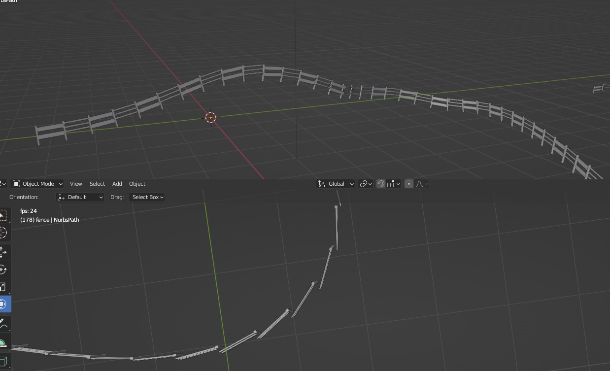
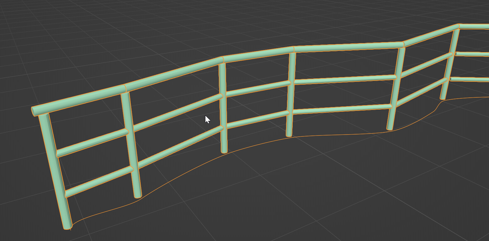
Looks good.
But from top view there is apparent gaps because fences do not orient to the next fence.
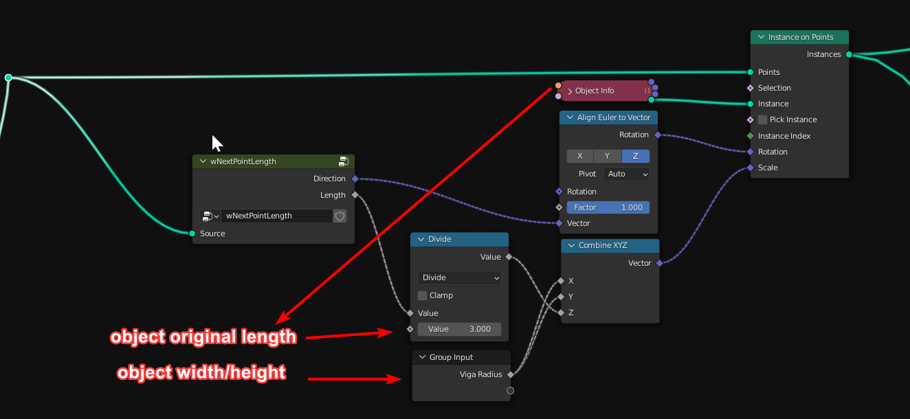
Is there a way to align object instance to next object instance ?
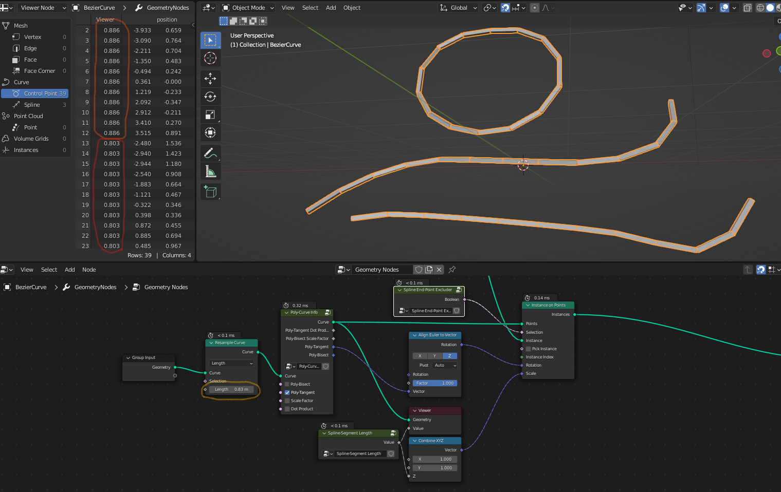
To align to the next instance I’ll do it this way : you need to access the next point with a field at index node, then create a vector by subtracting next position with the current one, and use it in an align euler to vector node. But there is probably a simpler way of doing it in the tutorial.
The curve tangent should be already pointing in the same direction.
I suggest you redo it or investigate why it works in his case.
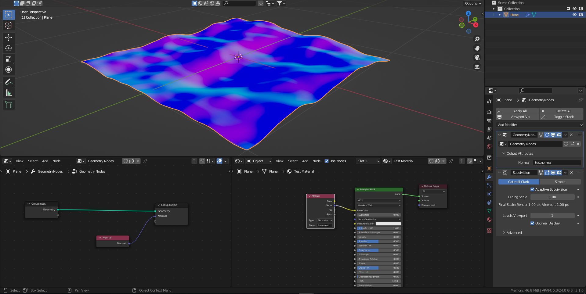
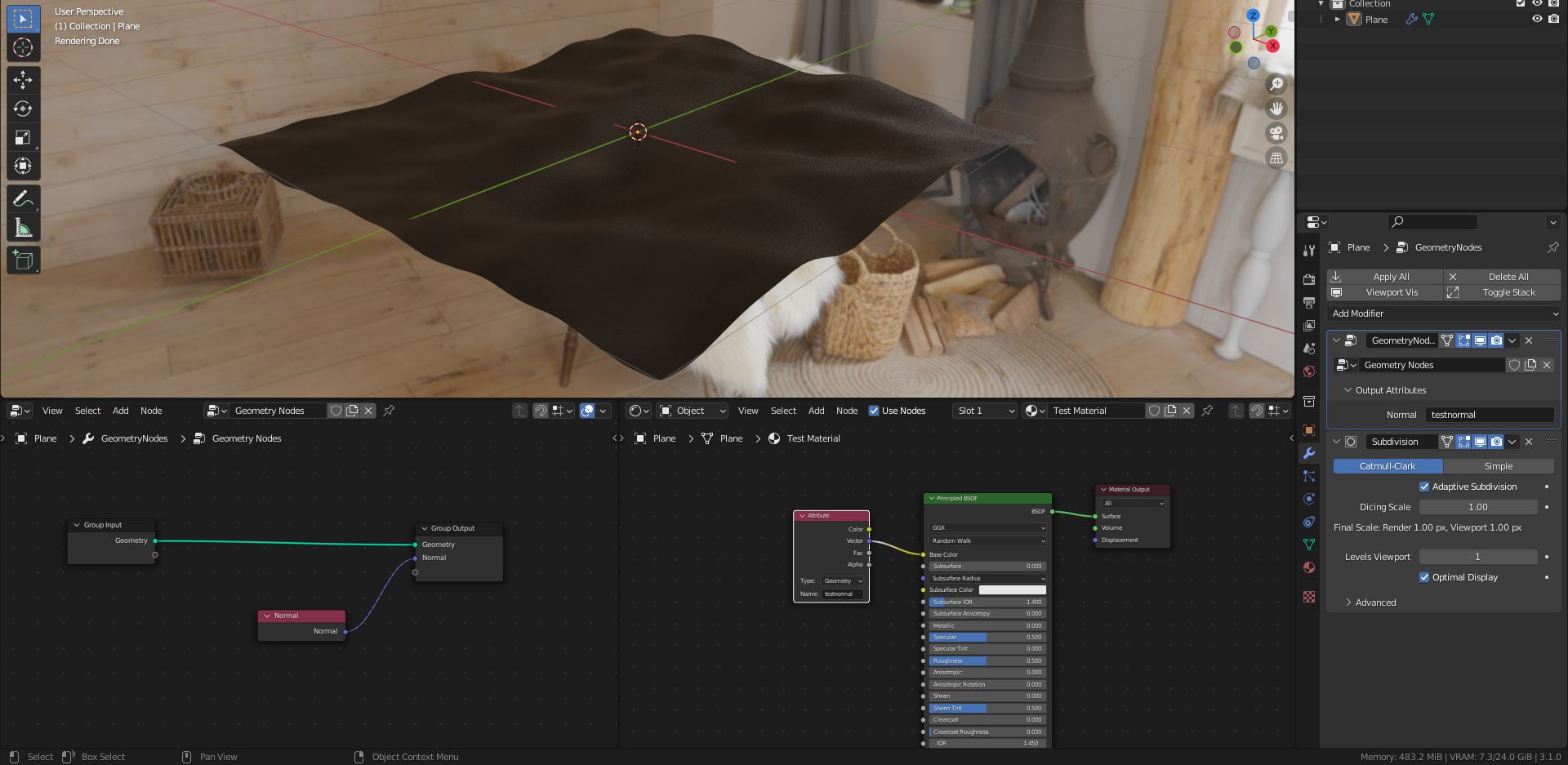
Hey guys, I’m pretty sure this is a bug but in case I’m just being stupid I’m posting this here too. I’m having the issue that, when I render with adaptive subdivision, any attributes I’ve passed from geometry nodes to the shader editor are lost. For example, in this test file I have passed the Normal from the mesh to an attribute, ‘testnormal’, in geometry nodes. I’ve then used the attribute in my shader, and this works fine in material preview and rendered view with normal subvision. However, with adaptive subdivision, it goes black. Is there a fix for this?
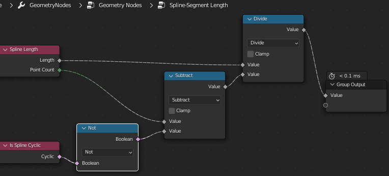
Yes, you can use the domain size node to get the point count , so you know the last index…
Then maybe by using the same technique with field at index you get the orientation value of the penultimate object, and apply it to the last. Or simpler, just delete the last point or instance.
If you really need it I can look at it, but it could be a good exercise if you got time to learn !
Interesting !
It’s probably not implemented, I don’t know if it’s a known missing feature , planned todo or simply a bug (like this was working before and after a rewrite it doesn’t anymore) .
You can try with vertex color , because it’s similar to attributes , to see how it react, and try to submit a bug… Could be great to test it in latest master (3.2 Alpha) and an older version like 3.0 / 3.1. To see if that’s already fixed, or if it was working before.
I tried changing the output attribute type in geometry nodes to colour and then reading the attribute in as a colour in the shader editor and now it works! It seems like the issue is only with attributes written to vectors.
@higgsas
Hi, the blend file you attached does not give the result in the image.
I use Blender 3.0, maybe that’s the reason?
Object “Plane” has no visible geometry in the viewport. (tabbing into edit mode shows me a plane alright, so does disabling the geometry nodes modifier)
Hi, yea the “3D points grid” node group fails because of “Float Compare” node is different in 3.1
Here is test file for 3.0 points_inside_volume3_0.blend (119.5 KB)


")