Problem with the measurement/position of centered text.
I don’t have the latest version on this computer so perhaps this problem is fixed already.
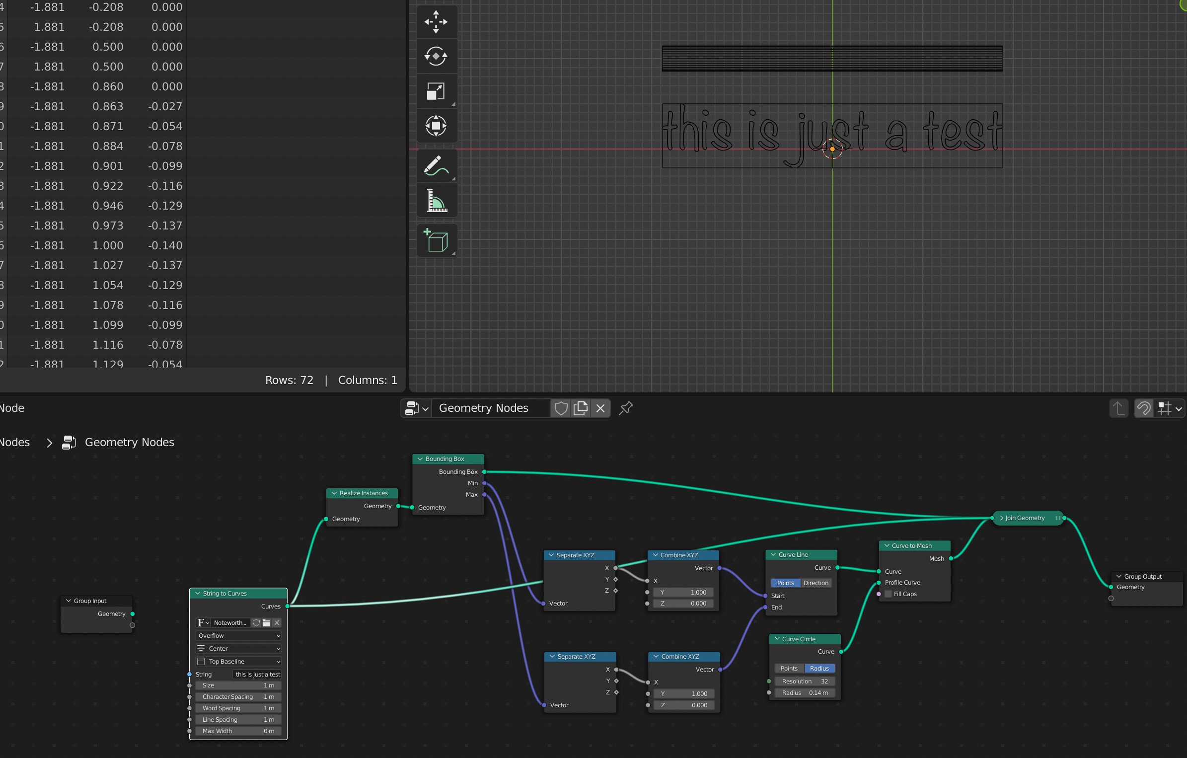
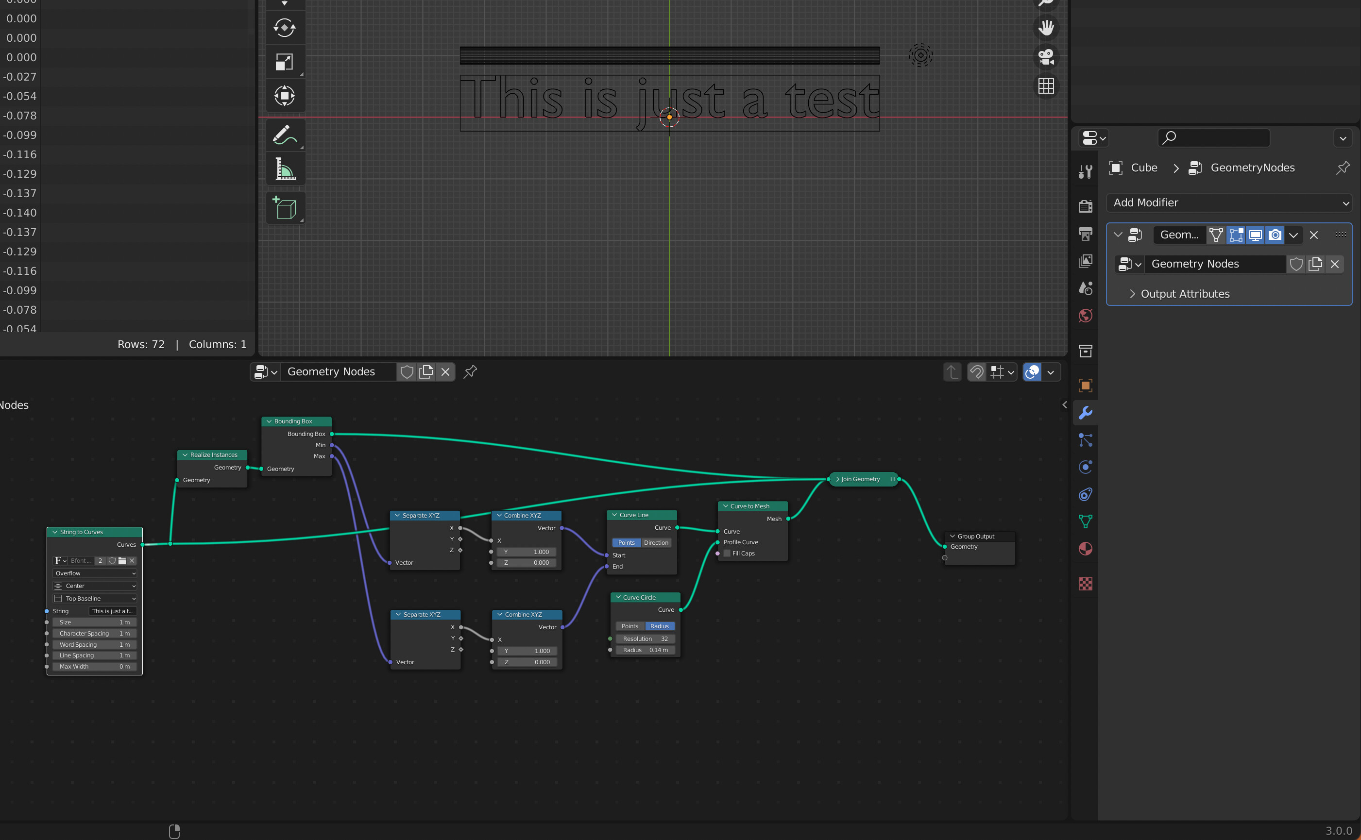
I have a text input box on the geometry node modifier.
String to curves node with alignment centered.
Fill curve > Realize Instances > Bounding Box
Get the min X, max X, and distance between them. (width of the text)
Make a mesh line with 2 verts. Offset is the width of the text. Start Location is negative half of the width of the text. Use Mesh to Curve > Curve to Mesh to give the line some thickness.
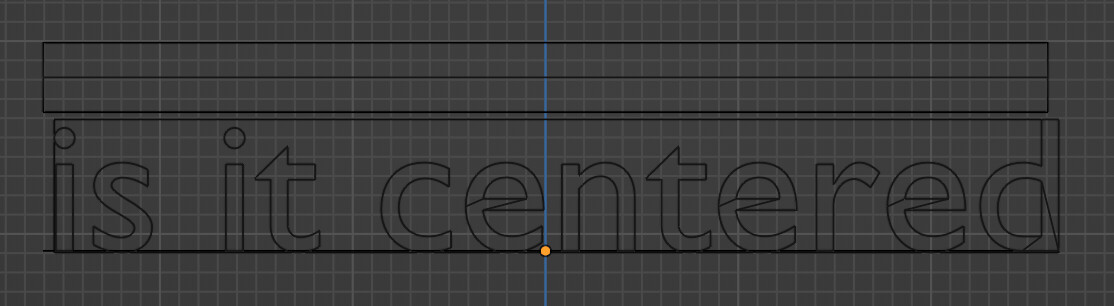
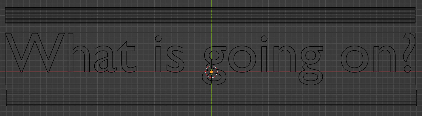
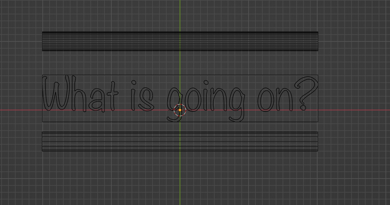
The line is never exactly positioned center aligned to the text or the bounding box of the text.
The offset is caused by your mesh line setup (reasonably) assuming that the text is perfectly centered. When looking at the Min/Max output of the bounding box node though you’ll see that the x values aren’t perfectly symmetric:
Min x: -3.625
Max x:  3.582
So your mesh line is indeed perfectly centered but the text and the curve line using the Min and Max outputs directly are not.
I feel like the bounding box displayed for a string ending in spaces is different from the actual bounding box measurements returned. Spaces in general seem to be handled wrong. I’m getting a lot of bouncing around even though I’m using a monospaced font.
Blender really needs a proper way to export curves for Geometry Nodes interoperability with other packages. And an offset node, although there’s one for 2d curves over on youtube.
E: Oh and the option to fillet particular curves with a certain radius rather than all or nothing.
I converted a bunch of points to volume in Geo nodes using the points to volume node. However when I try to render them in cycles I can see the whole voxel around the volume… is there a way to fix that?
I tried using the density attribute in the shader, and I can see something changing inside the voxels, but they are still visible.
Hey guys, I’m following the thread and it’s very inspirational. I got some answers to my issues on geonodes thx to you all.
I decided to post my project here to have some feedbacks and help as I’m stuck on a certain number of things that does not work as I want it to.
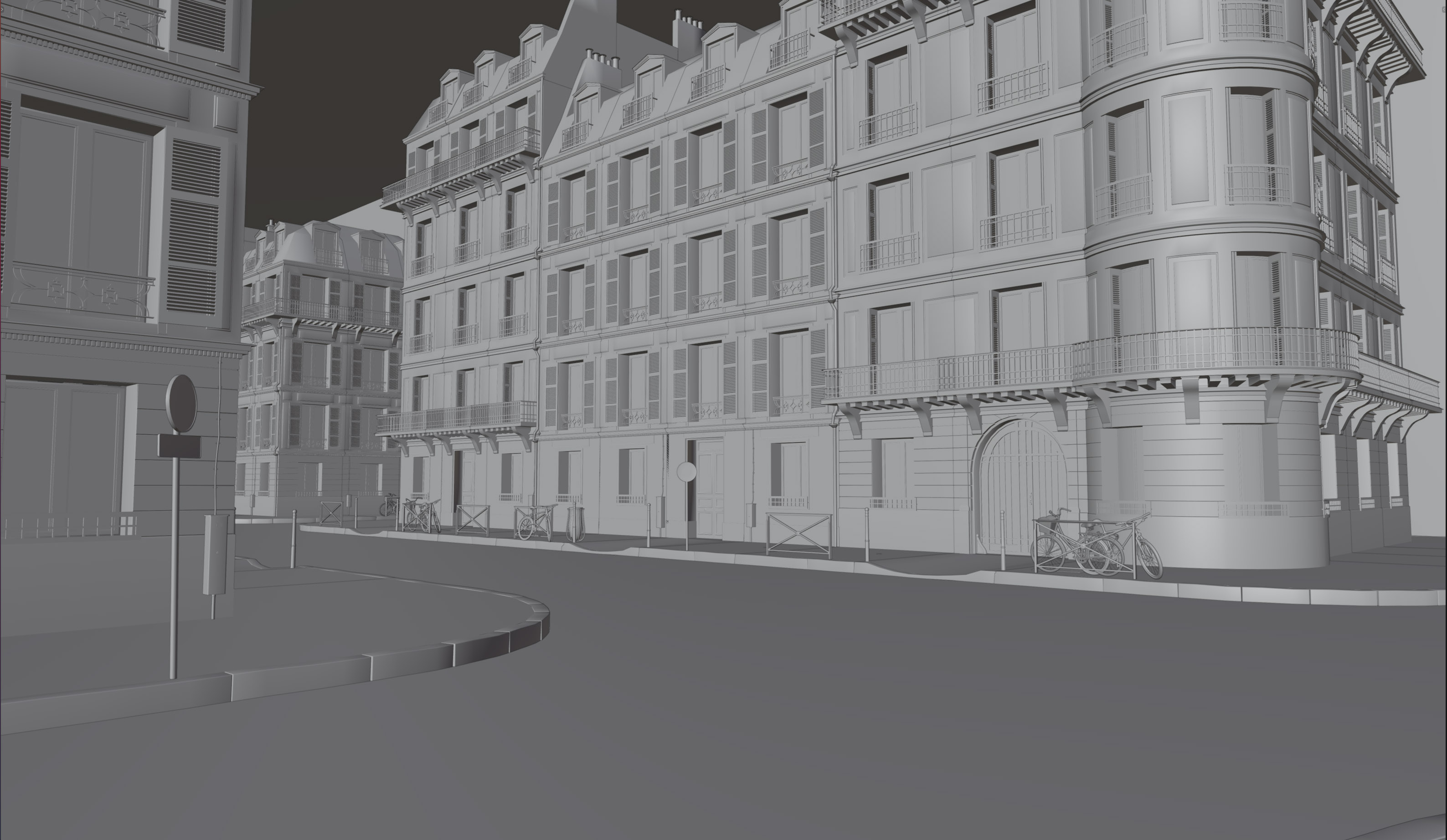
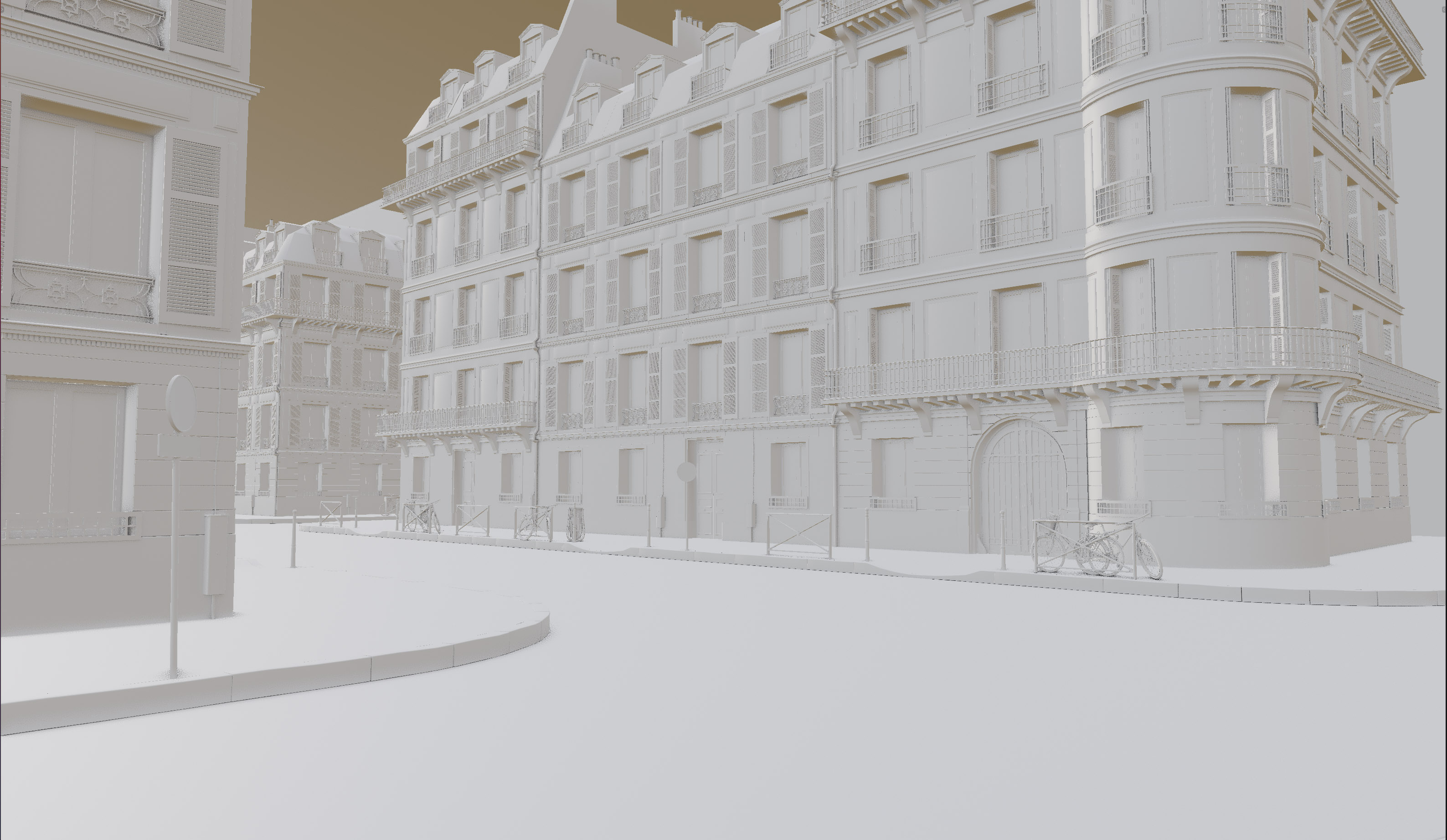
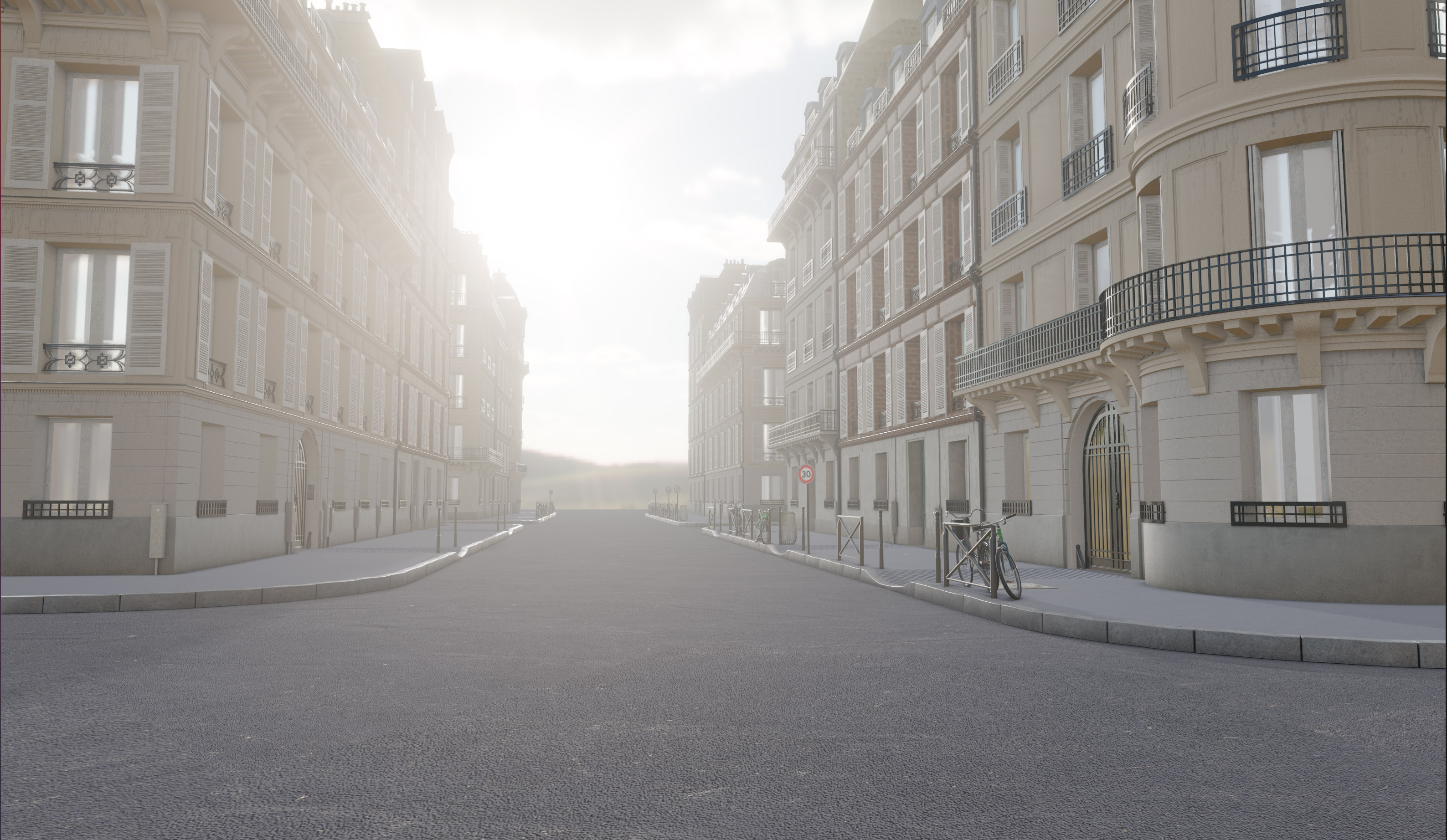
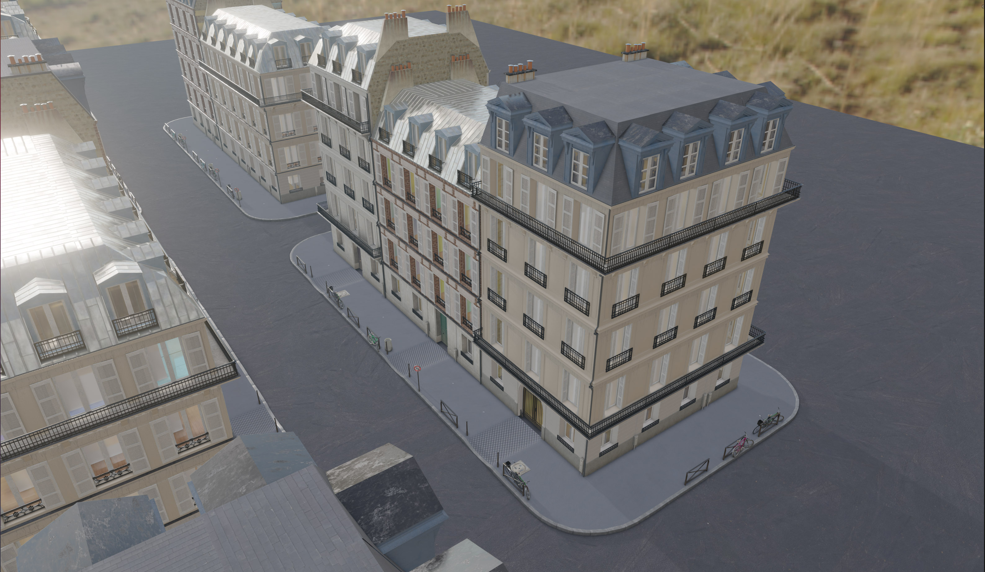
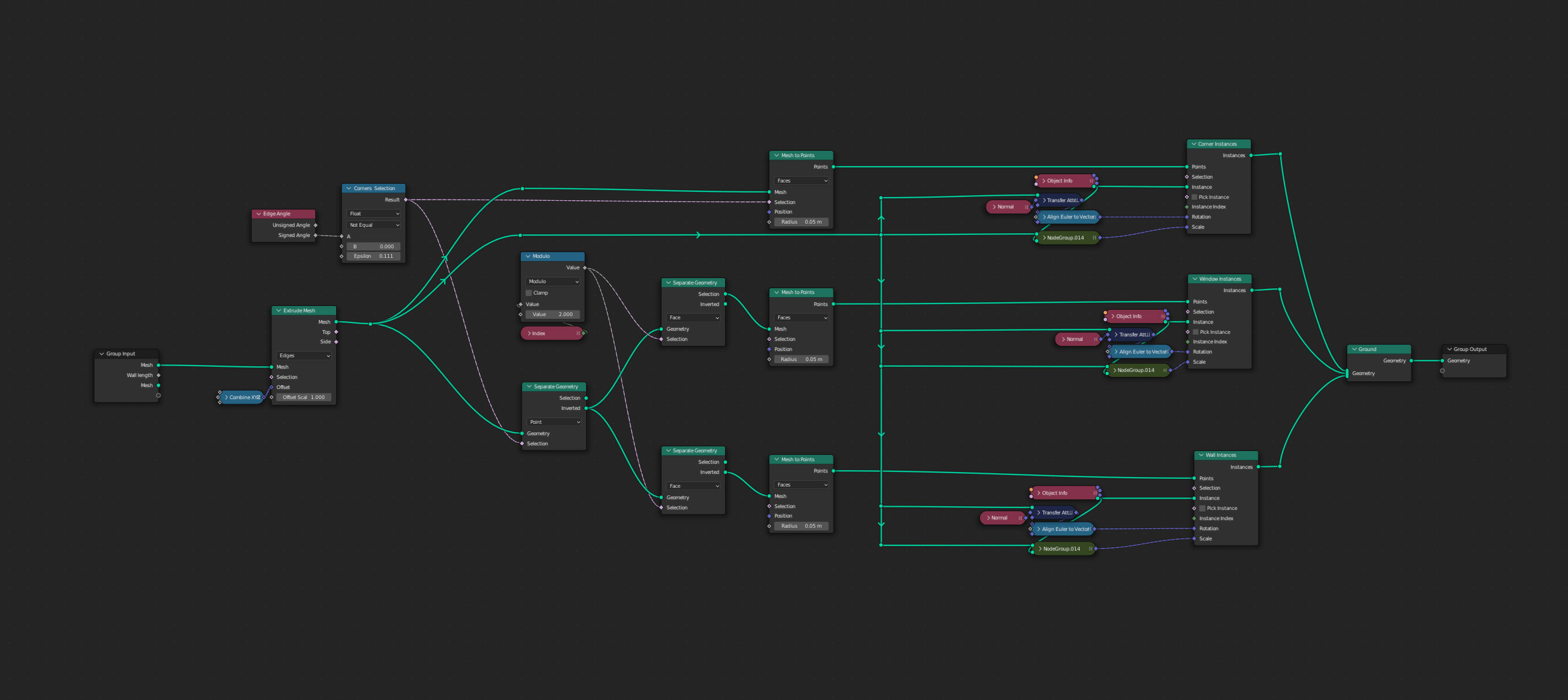
I’m working on a Parisian Building generator.
At first I followed a super tutorial found on Youtube that introduced me to geometry nodes and the principle behind the famous building that can be sized on x,y and z but must remain pretty rectangular. No fancy walls with angles or complex shapes.
It was a good start and I’m pretty happy where I pushed it with some specific option etc.
As you will see there are some issues I need to tackle still.
Born in Paris and having lived there for 30 years plus I was not happy with the fact that the building could not be placed and shaped in an organic way.
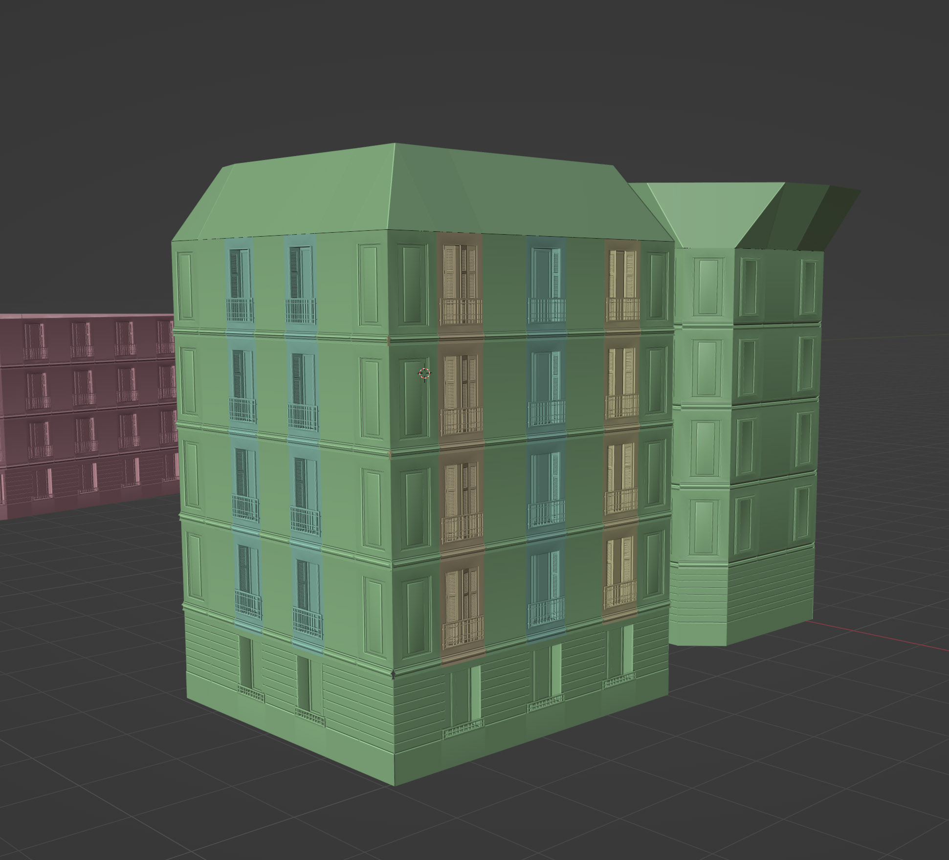
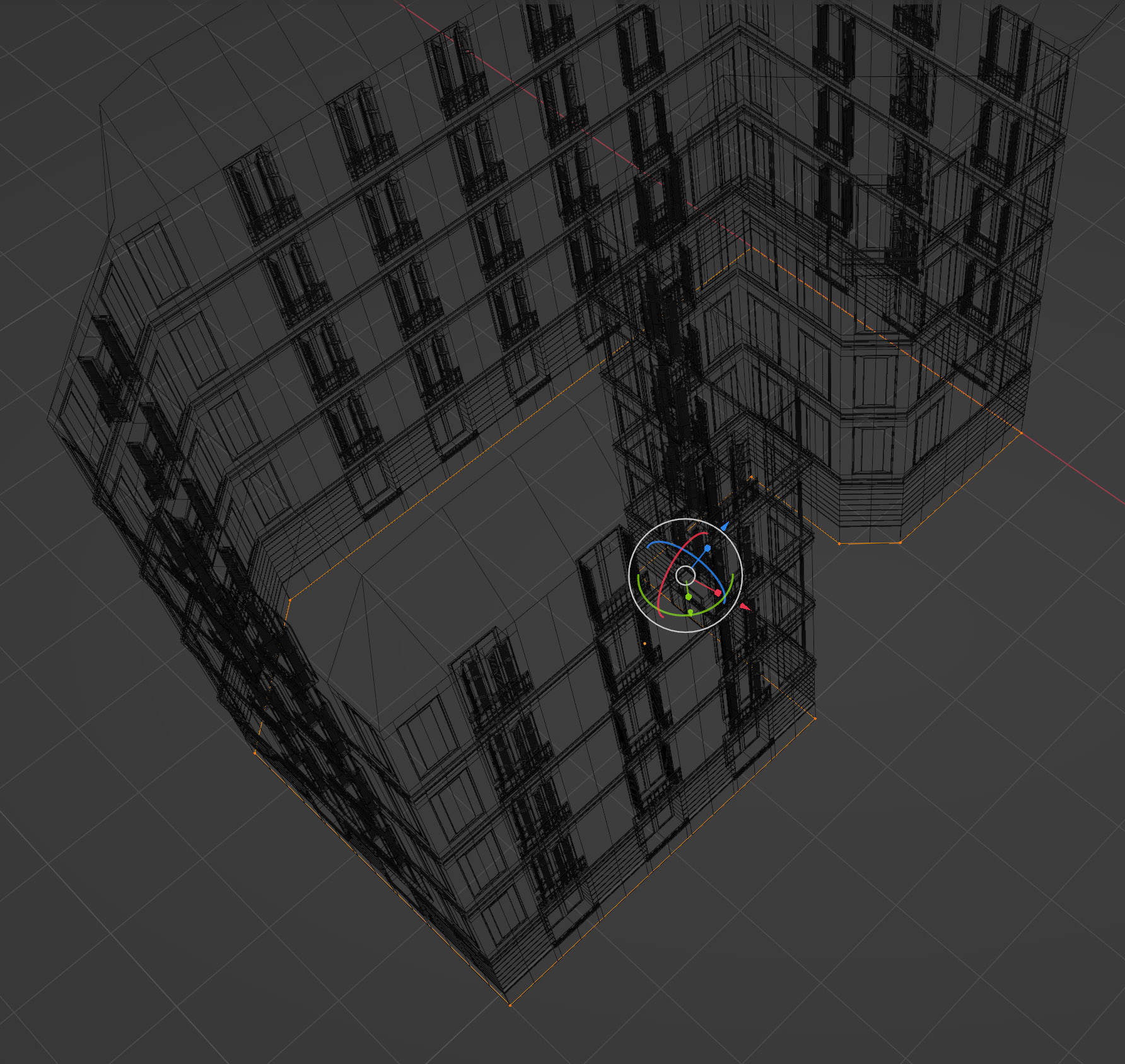
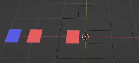
So I decided to change completely the approach and go for a flat mesh area that is extruded.
I kind of landed somewhere it’s taking good shape but there are lots of things I want to sort before going further.
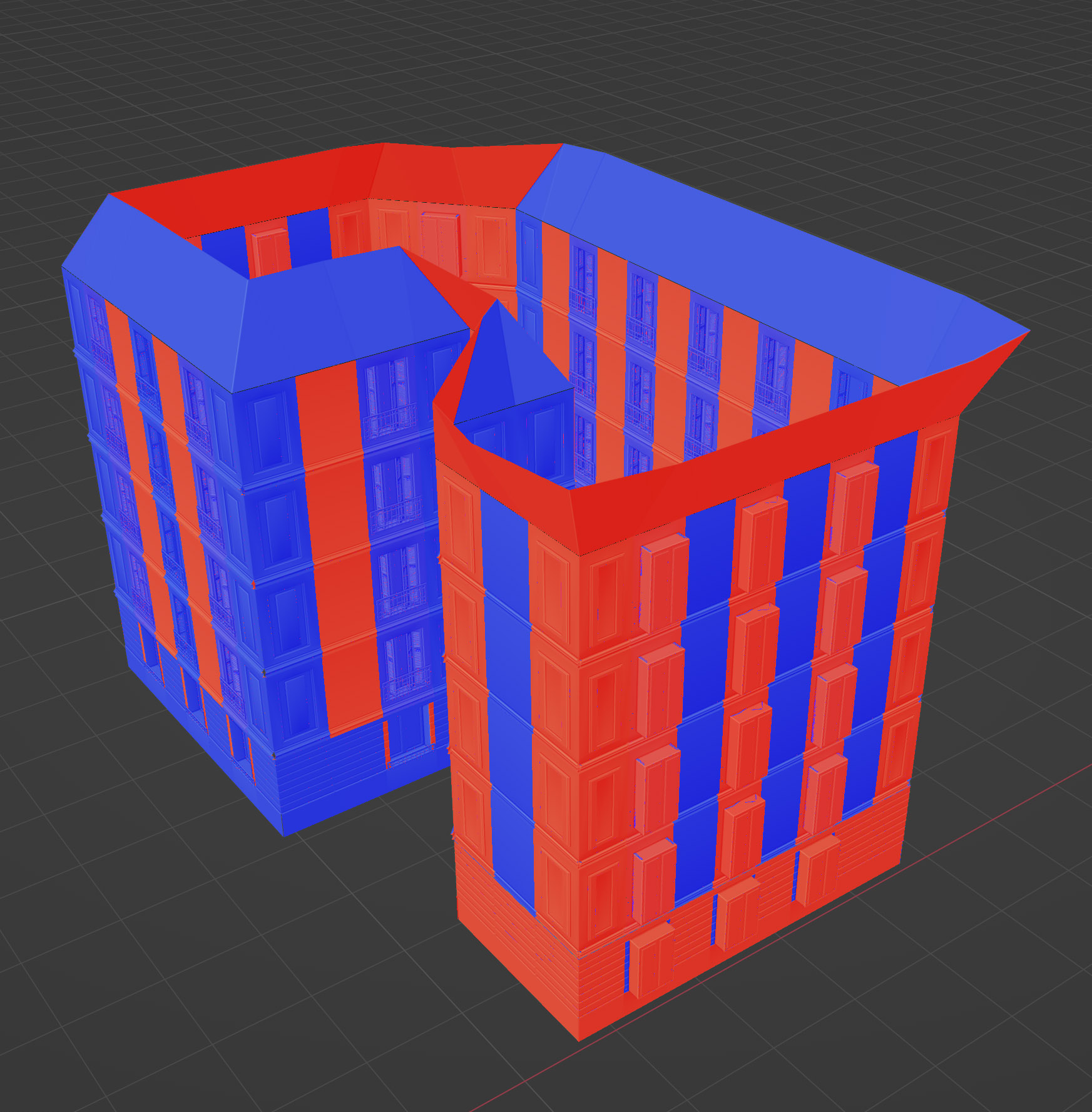
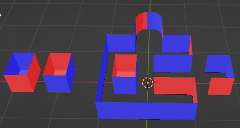
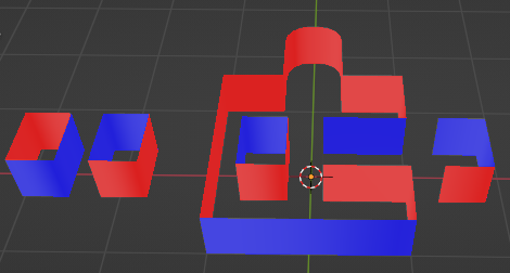
As I start from a wire not filled by a face (to not have the issue of tilted corner when converting into curve to resample without subdividing the height) I can’t get it right. Tried a lot of things but nothing gave me good normals. If I fill the base with a Ngon I get correct normals but bad corners when extruded (nor straights).
So if someone knows a way to tweak the normal after the instance or extrude… I’ll love to know.
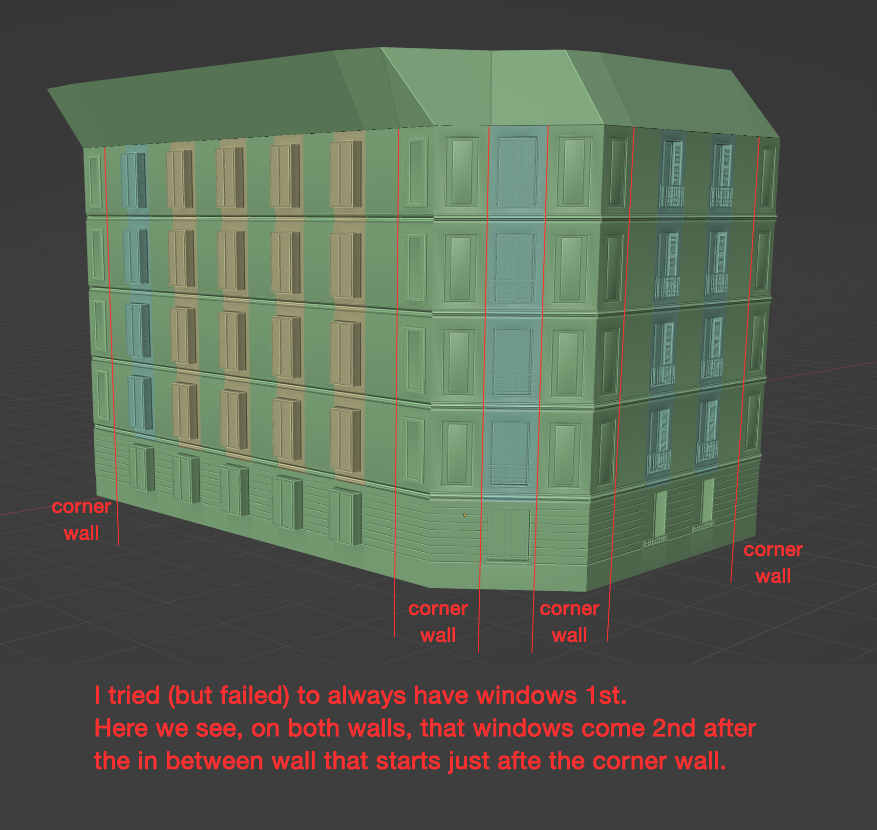
2nd the face rules:
I tried to establish a rule which is this way : Each side of a corner, you have a corner instance.
Then I want a windows (alway) right after it, followed by a inbetween wall instance.
I can’t get it right. At all. It works on some islands but not on others.
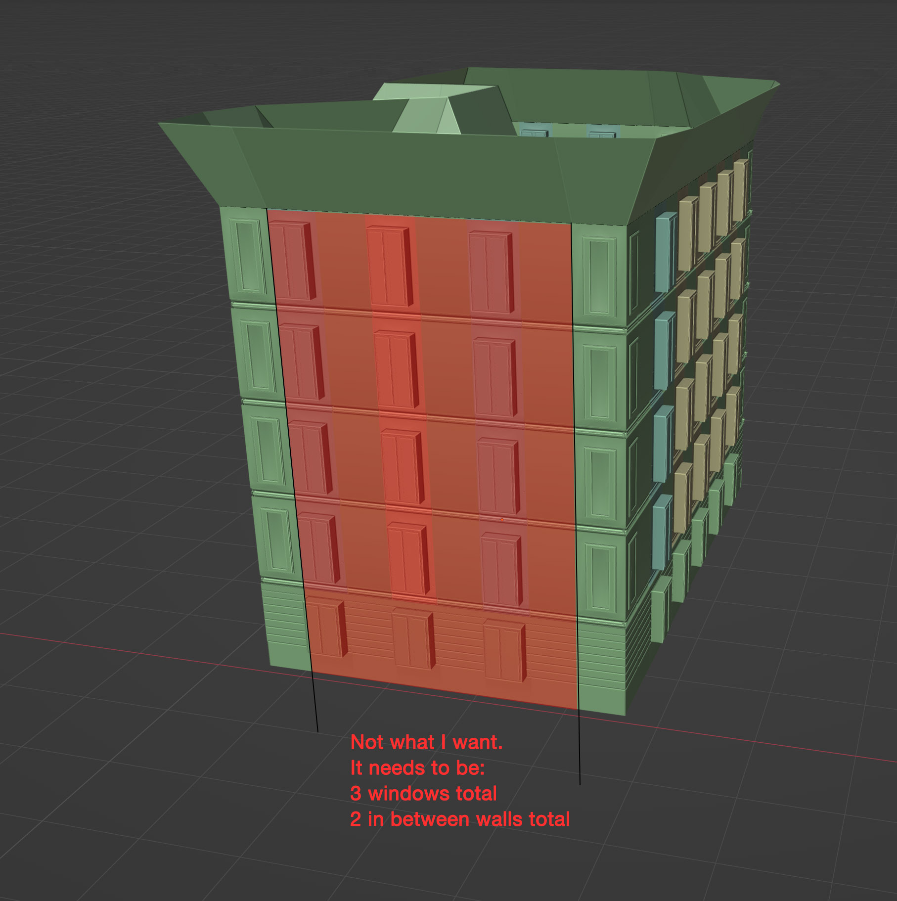
In addition to that, I want to always have a certain number of faces to always have a window 1st and a window last with at least a in between wall between.
Yeah I know there are quite a lot of things I can’t get right so if you guys have some bit of advices or answers to these very surprising issues to me… I’d love to hear.
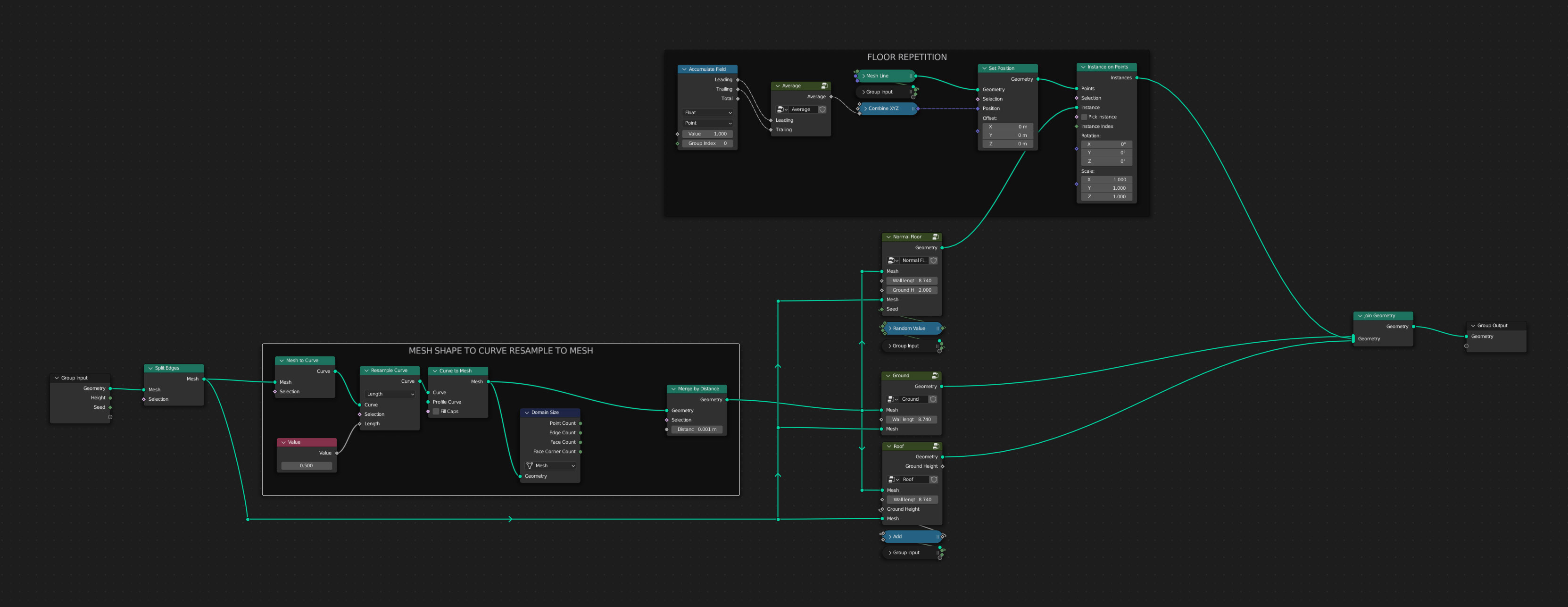
i love geometry nodes and i would like to help, but i am also pretty lazy. So if you would provide your blend file (can be a “shortened” version of just your problems) so that we don’t have to rebuild everything outselves…i would gladly take a look…
Are there plans to allow users to use Python code directly for Geometry Nodes? It could be called “Geometry Scripts”.
I think it would make less-than-trivial node setups simpler to craft and understand, and Python coding is also useful knowledge that can be reused elsewhere. One thing I really don’t like about GN is that it it’s too much Blender-specific and not so intuitive despite appearances.
Hi
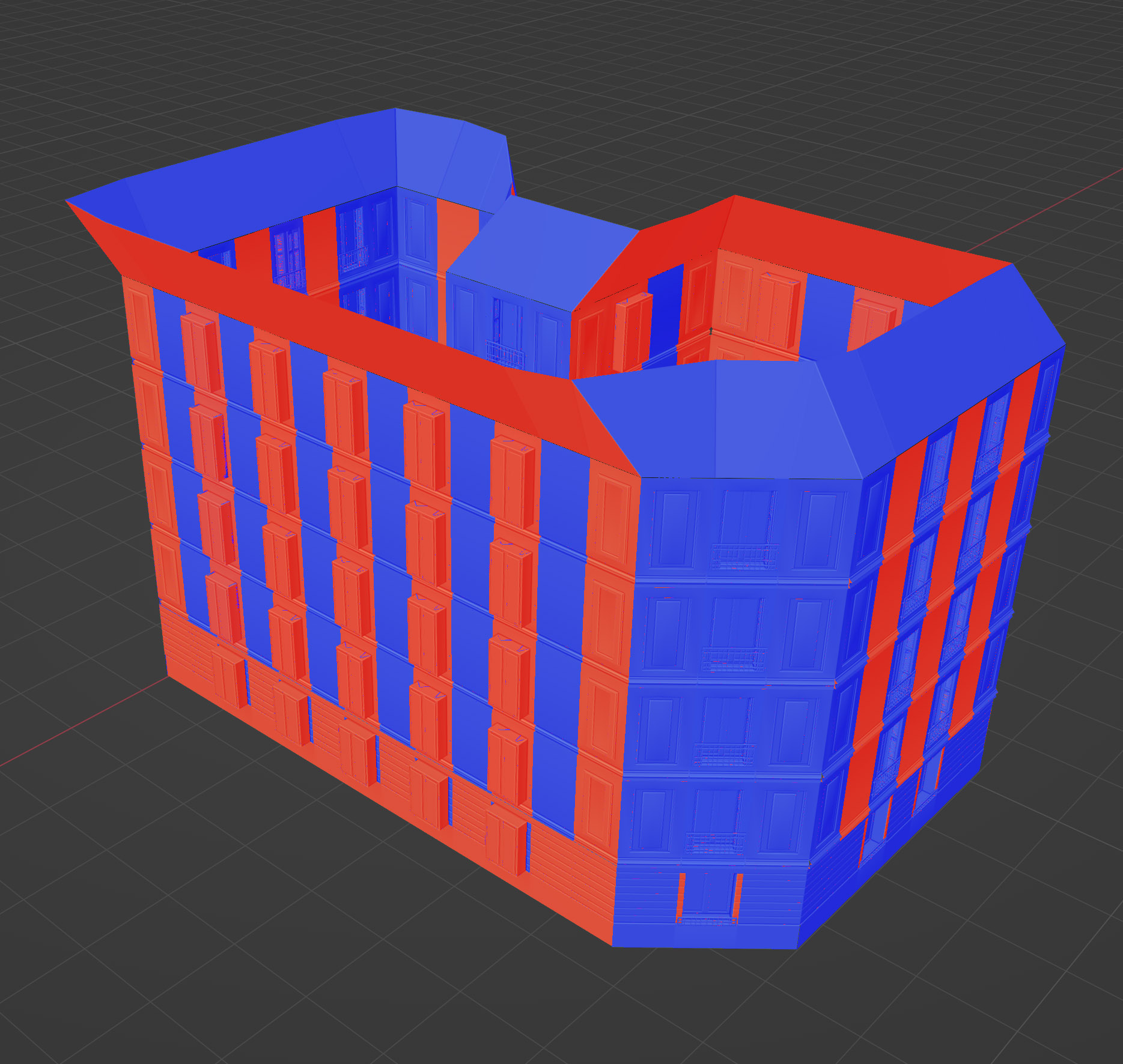
The following will only help with your inconsistent normals:
When you have a base-curve/mesh and you extrude the edges, you’ll get inconsistent normals… a trick to overcome this issue is to start with a curve-to-mesh with a curve-line primitive (which has consistent normals), and then do further extrudes on that.
E.g: Using this base:
With extrude edges ((0,0,1) offset):
With mesh-to-curve->curve-to-mesh (with (0,1,0) line profile):
Also, at any point, you can use the flip-faces node on a selection of faces… so you can compare your normals to some reference normal and flip any that based on whatever math you can come up with.