Hi! I’ve been using geometry nodes to build city blocks that instance pre-made shapes on blocks. I’ve made a few variants of them, but I’m working on one that’s proving a bit tricky.
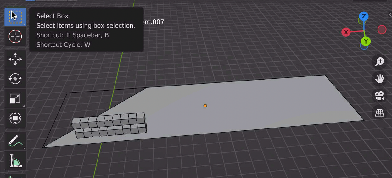
Some of the blocks I need to make have angled edges (all the others I’ve built are right- angled.) as below:
So far I’ve split it into several sections to try and make it work (probably a really hacky way) First of all I subtracted the difference in the y and -y lengths to create a chunk which I can drop my right angled block generator into as below:
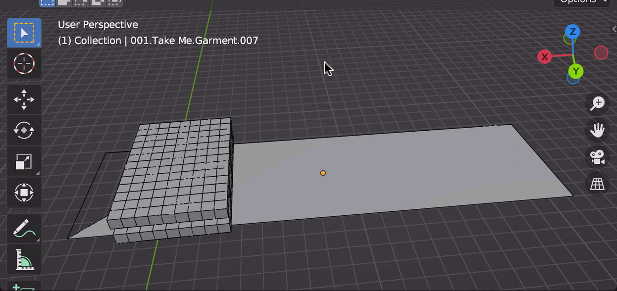
But what I’d like to know is, how do I find out the angle of the angled edge and how can I translate that to the rotation of the final ‘block’ as below:
“Edge Vertices” are coming to the rescue once again!
By subtracting positions you will find a Vector pointing from one vertex to the other. In one direction or the other - it [probably] should not matter in this case.
Another helpful node is “Align Euler to Vector”.
It returns a Rotation from some Axis to input Vector. In my example I rotate X-axis to the edge.
With that you can then rotate and set Positions of the block… at least if simply rotating around the Origin.
(Or, if it’s an Instance, plug the rotation straight into Rotate Instances node).
Thanks for the quick reply and for the advice again!
Unfortunately I’m not getting any rotation when I replicate your node set up and plug it into my block. I tried toggling through the indices on the sample index node but my block is just staying in the same position.
Instead of plugging into the vector rotate and set position, I plugged the output of the sample index into the ‘translate geometry’ node from the third block node tree!