Hey, thanks for your interest! I’ve actually been lurking on your thread ever since I noticed it was gaining traction again, hah.
Just to make sure I understand correctly, you want to calculate for the reflection off the backside of the surface facing the onlooker?
If so, yes, this implementation does deal with that! When we see any backfacing geometry, the node group flips the layers. Say we have a stack described by: Air, Film1, Film2, Substrate. At backfacing geometry it changes to: Substrate, Film2, Film1, Air
Although, I will say that in the recent discussion pruster and I had, we talked about the propagation of light within absorbing media (such as metals and semiconductors), and the conclusion was that light is absorbed very quickly. There is no need to calculate the reflection off the backface of a metal.
If you end up using this node group in your renders, I’d love to see what you come up with!
Oh wait, I realized you said, “destructive interference”. I missed the “destructive” part, hah.
This node group does deal with metals correctly. With materials that have a complex IOR, all you need to do to account for it is use complex math. The functions will be able to take the complex part into account that way.
Just wondering, which part of the math is confusing? I’d love to help you! Math is one of my favorite things to do and is one of the biggest reasons I made this node group!
For reflectance: R' = R (exp (-4 pi k d/lambda))^2 = R (exp (-8 pi k d/lambda))
(Light travels toward the boundary, through the incident medium, light that’s left is reflected, travels back from the boundary, through the incident medium again, to reach our eyes)
For transmittance: T' = T (exp (-4 pi k d/lambda))
(Light travels once through the boundary to reach our eyes)
Are those correct assumptions to make?
I almost forgot to ask, but why would k not be the imaginary part of k_z? Although, I’m realizing that maybe I should have said the imaginary part of n cos(theta) which is equal to (k_z)/(2 pi / lambda).
Despite that, the idea is that the attenuation within a layer is described by the imaginary part of those values (with the correct respective formulas) through the OPD, so why wouldn’t it work similarly within the substrate?
Or does it work that way only within a layer? Or were you speaking from normal incidence?
Hey everyone! There are no updates for now, but depending on the how things go for the next week or so, there could be one.
For now, I’ve created a few animations of various parameters of the thin-film interference node group changing. They’re really fun to watch!
This is a bubble within glass with the bubble’s refractive index increasing. At some point, the refractive index matches the glass, and the bubble disappears. Similar to that experiment with glass rods disappearing in oil when their refractive indices are similar.
This is an air bubble in glass with an increasing refractive index. The colors of the film change throughout the duration of the animation.
The following is a bubble with increasing thickness.
This next one is an example of absorption in glass. It shows how using the ‘k_I’ parameter of the object inside (in this case, a ball of gold) in conjunction with the ‘k_S’ input of the surrounding glass work together to create an absorption effec - it’s a DANCE PARTY!!!
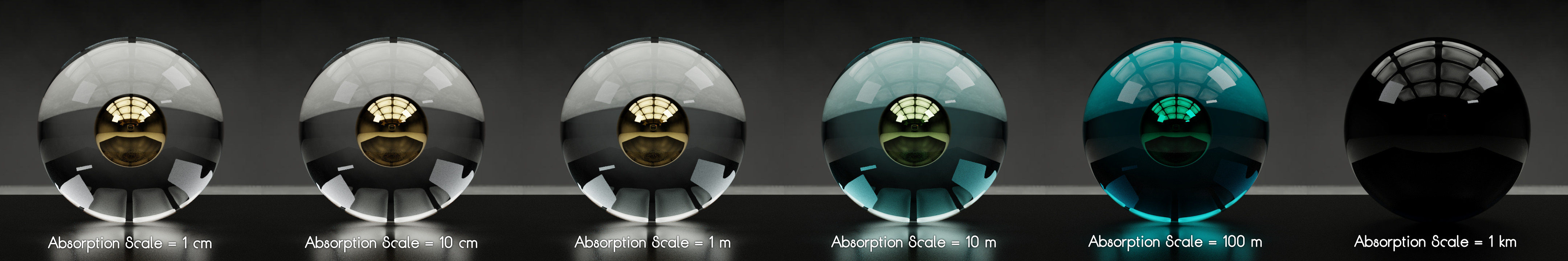
My favorite one is an example of how the ‘Absorption’ input affects absorption. This parameter controls the scale of the absorption. Using the physically correct refractive indices of water at specific wavelengths, we can accurately simulate the absorption of water as the depth increases. Water has a very small extinction coefficient, but that’s what gives it its color (I didn’t realize this until I played around with water’s refractive index in the node group).
The ball inside is also gold… sunken treasure?
Here are the depth values and their respective images:
The final image would be an example of a situation were the absorption is so high, a refractive shader would not be needed anymore. The colors would probably be slightly different for salt water (likely slightly greener) because the salt would change the refractive index.
I have never put in the time to really understand complex IOR, but your tip that the imaginary component is just absorption definitely helps. I think my knowledge of the behaviour of waves at boundaries (to phase shift or not to phase shift) is a bit lacking, too.
Your latest examples look spectacular.
I have a question regarding real-life materials and their IOR. You stated that K_I is equal to the absorption. Is there any way to derive the K_I of a material at a particular wavelength from some other property it has, or is this data exclusively measured from physical materials? How have you represented the complex IOR of water to give it a realistic absporbtion colour?
There’s a bit more to the imaginary part (such as how it can affect the angle of refraction), but yes, it does, in general, describe absorption. Oh, and the phase shift is described by the δ in the equations I typed up. Normally, δ = (2 pi d / lambda) (n + ik) cos(theta), but δ in the equations I describe is what allowed R+T=1 (energy is conserved) when the films all have a real index.
I’m actually trying to get a reliable verification of the formulation I use, so that part might change.
I do remember @prutser mentioning a relationship that connects the real and imaginary parts of the refractive index. It’s called the Kramers-Kronig relations.
I input the values for the refractive index I found here into n_S and k_S then increased the Absorption. The Absorption takes values in nanometers, so if you want a distance in meters, you’ll need to convert accordingly.
On a side note, I will say that the upcoming update might, yet again, change much of the formulas used to calculate interference. I was told that the transfer matrix I use can become numerically unstable, so I’m working on implementing the S-matrix (still in the “trying to understand it” part, haha).
I will eventually be updating the collection of equations I typed up, but if you want a head start at looking through the implementation, here’s the resource I’m using: Click! (only up to lecture 5). The videos really helped me understand the implementation.
Update v2.2 should be coming soon when I finish writing some detailed documentation for it! The update implements a more stable modification of the calculations, fixes a bug in the calculations for specific situations, and corrects the formulas for lossy incident media (which does change the look of some of the glass materials added in v2.1). Also, depending on how the tests for a new absorption formula go, there might be some different looks in terms of that (currently having problems with float values in the new formula).
Oops, maybe saying I’d have it “done soon” was a bad idea. Anyway, I have not yet been able to finish the detailed documentation, but here’s the update for now:
The changes in this update are described in my previous post. As for the problem with the new absorption calculations, I instead used the formula in v2.1 and removed an unnecessary step. Some of the glass materials have changed as a result, but they should be more correct.
I’ll be updating the top post when I finish the documentation!
I’ve took v2.2 for a spin with my new RTX 2080 and the overall speed is amazing. Render times are around 13-23 seconds with defaults from a file - 2.8 current build.
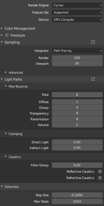
I’ve also tried materials in EEVEE and guess what. They are working just fine. Of course not glass ones, some of them. Some of them are crashing Blender. Here are some simple tests - Cycles top ones:
Wow! I never got around to testing it in the updated Blender builds, and I’m glad you did so for me, hah. Do you remember your Cycles render settings for these? I’d love to compare them to mine.
Never did I expect the nodes to work in Eevee, that’s crazy!
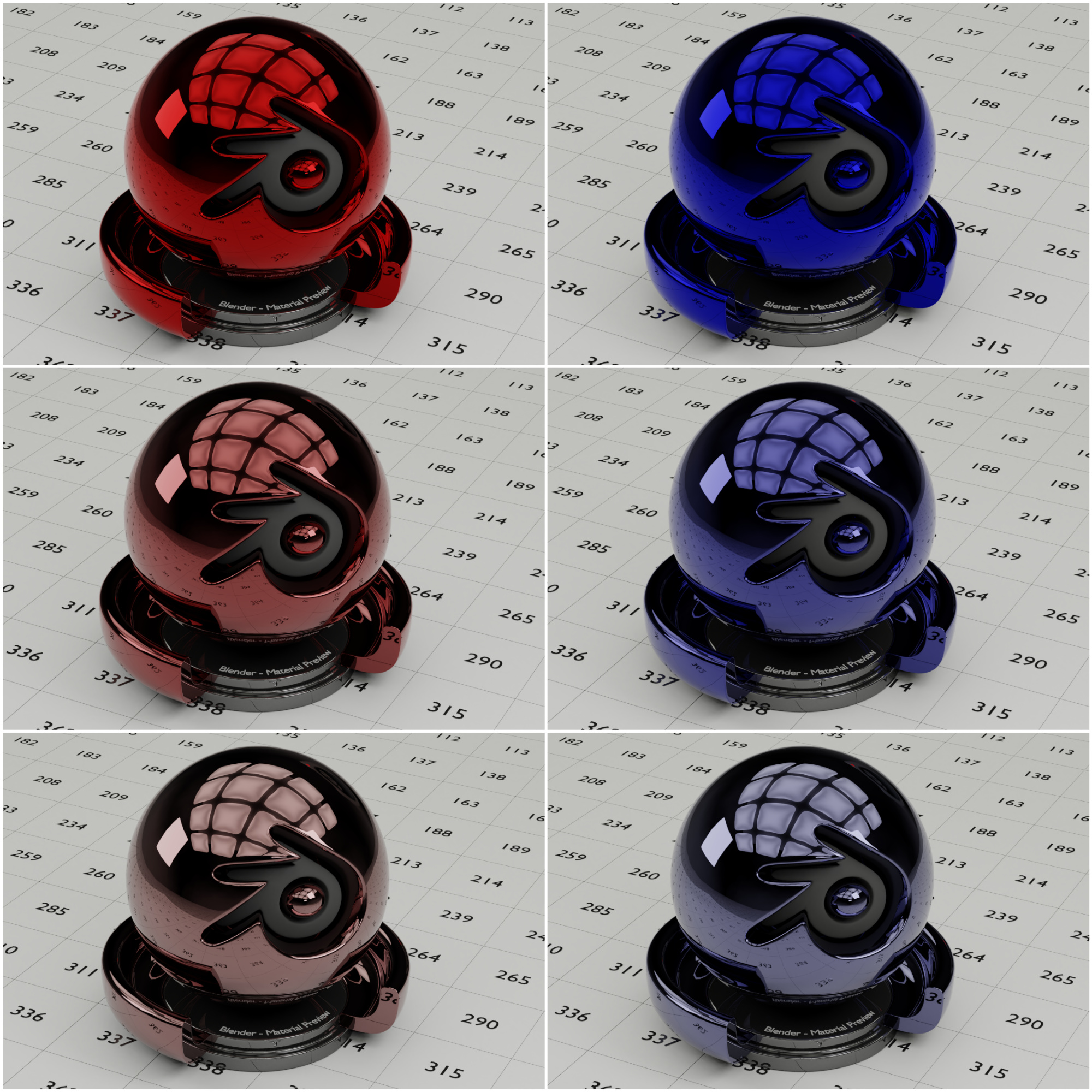
Also, I finally got around to making the renders for the documentation, so the true update should be coming ̶s̶o̶o̶n̶! Here is a preview of documentation for the effects of the complex refractive index:
I don’t know what caused so drastic changes in render times as I’ve lastly tested it on gtx 770 and blender 2.79. Now I’m using gtx 2080 and blender 2.8 daily.
It’s crazy fast, here is example from render preview:
I finally got around to testing a render in the most recent build of 2.80, but my results were actually slower than those in 2.79.
Results using the same red glass material:
2.79: 2.06.01
2.80: 2:55.58
Slowdown from 2.79 to 2.80: 139.34%
Results using car paint_1:
2.79: 1.53.06
2.80: 2:21.11
Slowdown from 2.79 to 2.80: 124.81%
I think the speed up may be from your GPU! Mine is a GTX 1050.
I also tested the materials in Eevee, and I was still surprised it worked despite your account! I also didn’t expect it to work for the 3 layer calculations, but it did.
It seems the problem with the glass materials is not necessarily the nodes but rather the limitation that Eevee cannot retrieve ray length, which is used in the absorption calculations.
Edit: I looked into it more, and it seems the optimal tile size for GPU’s is smaller. After some testing, I ended up with a tile size of 16 and a render time of 2:33.61. Although, as per your comment, you did not change any of the render settings, so this point is irrelevant.
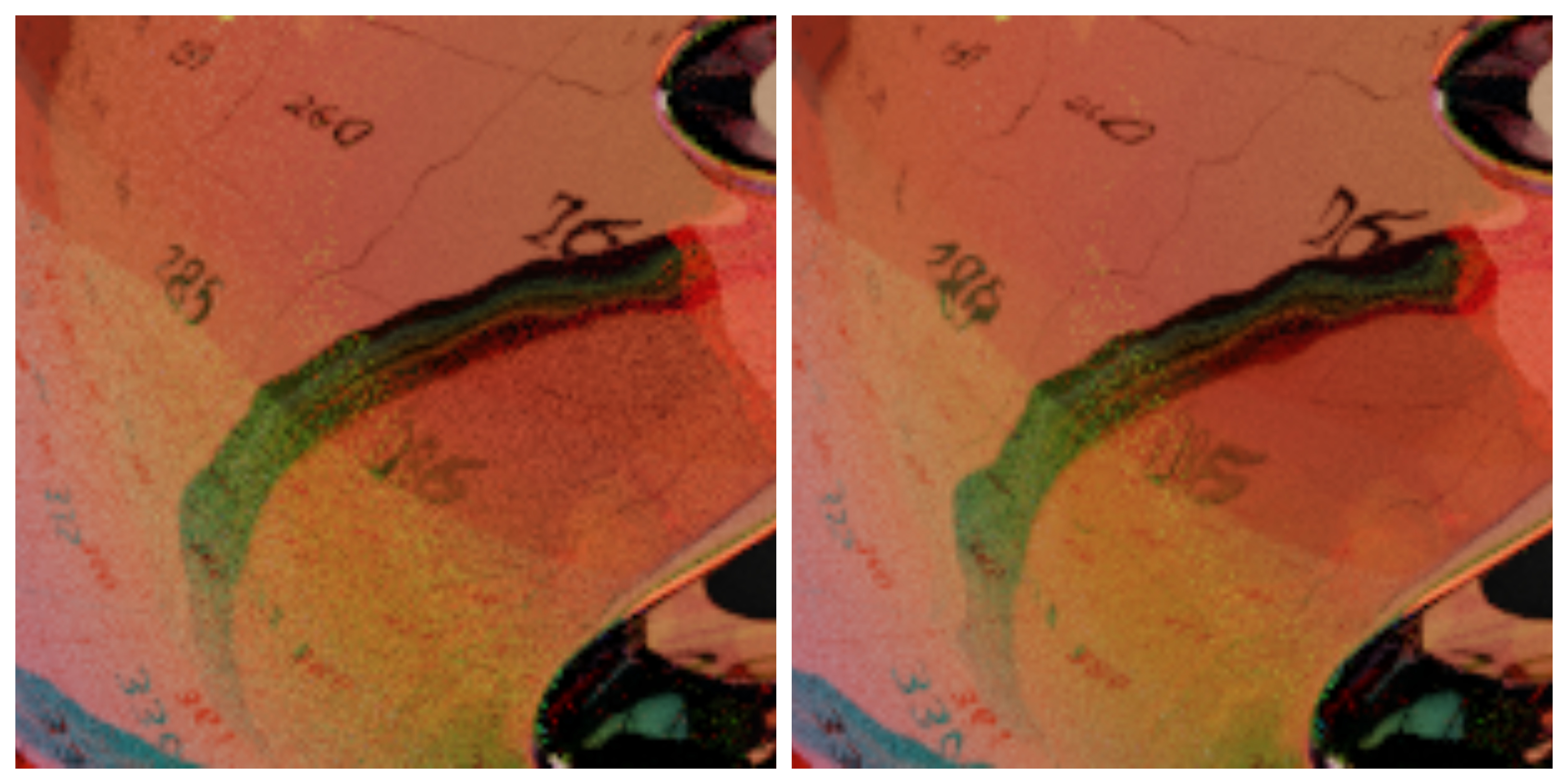
I also compared the noise between the 2.79 and 2.80 renders, and there is less noise in 2.80.
Would it be possible for you to compare your render times between 2.79 and 2.80 with the same GPU? I’m curious to see if your 2.80 results are also slower.
This thread is super-interesting, and I wanted to chime in with a question and a thank you for those involved.
I’m a Grad student in materials engineering, and I use blender to make a lot of my figures. I’ve been trying to make a material to represent processed silicon wafers for a while now, and this seems to be just the ticket, but I’ve been having difficulty getting it to work for my application. Is there additional documentation that I can look to for how inputs should be formatted?
I’d like to simulate the off-axis viewing of a silicon wafer with ~ 120nm of oxide grown on it.
I understand using the silicon_nk node to input into the substrate part of the shader, but I’m unclear as to the convention for why it has RGB values. In particular, if I’m making an input for silicon dioxide, should the input for n for monolayer films be simply the bulk n, or should it be the n at each individual pure R,G, and B for my given color space? Additionally, for the output, does it matter which shader this is output to? Should it go to a Principled shader, or glossy, and if it’s supposed to go to glossy, should it be summed in an “add shader”? I’m technically inclined, but probably have less than a month of blender experience under my belt right now, so I’m still figuring out how all these node groups work.
Once again I think this is phenomenal work, and am really grateful that it’s been offered up to the community. I can see this being an exceptional tool for simulating and showing thin film device fabrication in an accessible way.
Unfortunately, after so long, I still have not come around to finishing the documentation for this. In the case of materials, the RGB valued inputs are to simulate the change of the n and k across different wavelengths of light. This node group samples the interference calculations at 3 different wavelengths, so you would input a respective n value for each (can be done using a combine RGB node). You can check the ‘Wavelengths’ input to find out what wavelengths are being sampled and to derive your respective n values. Alternatively, you can change what wavelengths are sampled, while staying within the values perceived as red, green, and blue, to produce slightly different results.
Of course, for some materials, the refractive index varies little across the selected wavelengths, so it wouldn’t hurt much to simply use a bulk n value.
As for the output, in your case, you would simply plug ‘R’ into a glossy shader. We wouldn’t use the principled shader because it automatically calculates the Fresnel effect with its materials, and the interference effects are, in essence, a Fresnel effect. Cases where you would to use an add shader include effects like thin films on some dielectric material. For those, add the glossy shader to a refractive/diffuse shader that uses the ‘T’ output.
I hope this helps, and tell me if you have any more questions!