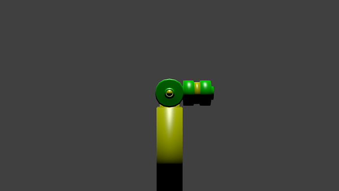
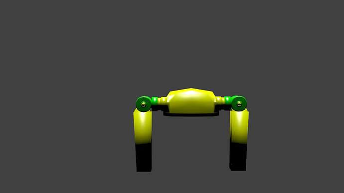
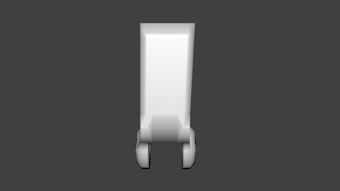
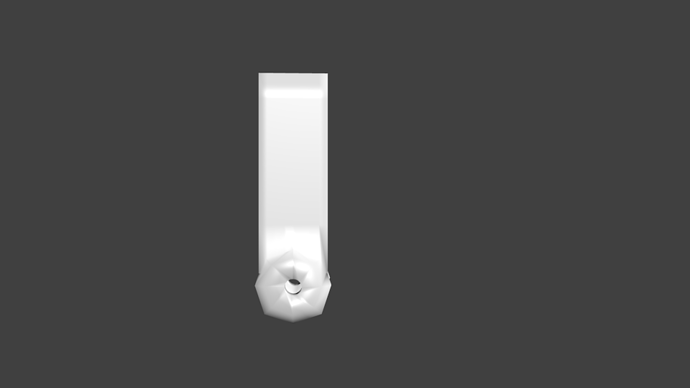
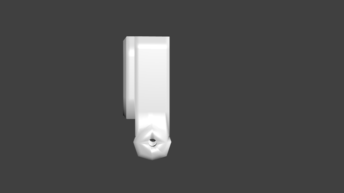
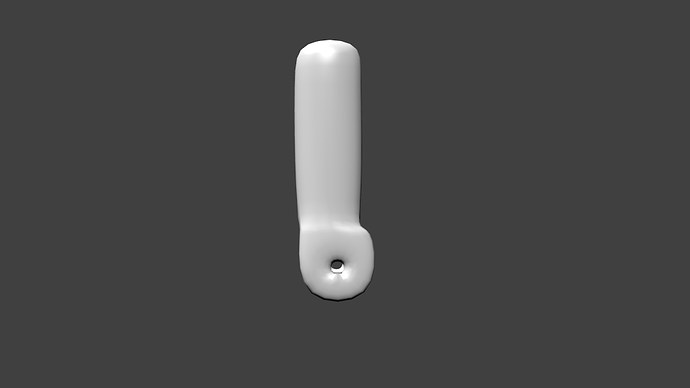
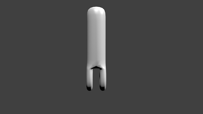
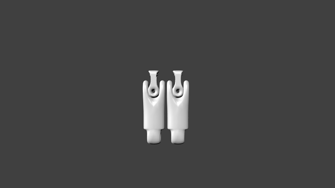
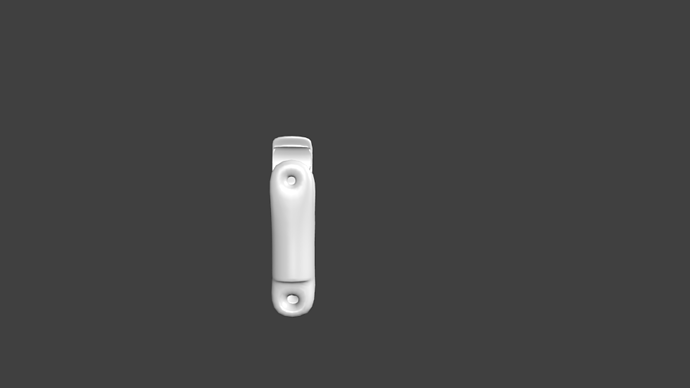
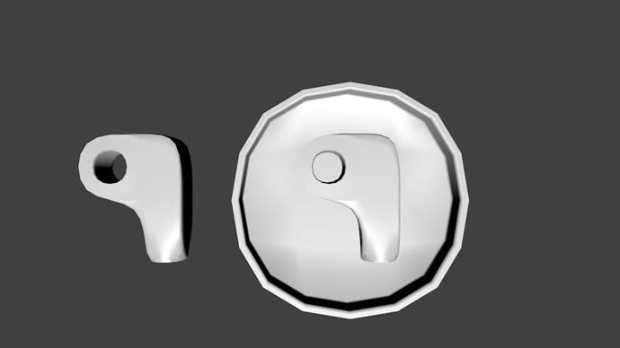
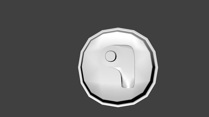
Here is a robot leg i made png’s of in color and wireframe.
Are you looking at or working from any kind of references? I’m assuming this is the hip area of a bipedal robot, but the re-creation of human anatomy is loose at best. The thighs seem to bend outwards, which doesn’t make any kind of mechanical sense; your robot can only do the splits. On a real human, the hip-thigh connectors are essentially ball joints with a very wide range of motion, and it’s the knee which has an axle joint. Take a close look at this little guy, I think understanding the shapes of real robots will help give life to your fictional ones. As well, take note of the kind of shapes that form the limbs, and how they flow and change along their lengths, and especially as they connect to their joints.
As well, you really don’t need to add colour or render fully yet; materials work is a complicated and involved process and its hard to see your model work under your garish lighting and colours. Just show viewport grabs; and wait until you’ve got a good headway on the modeling before you get into materials.
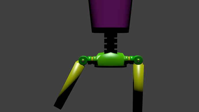
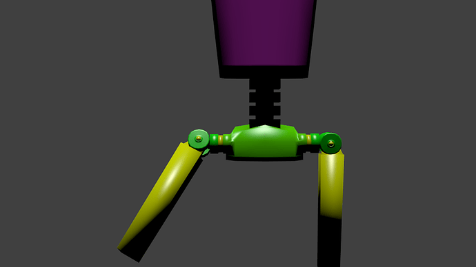
I am sorry that you did not understand the leg the first time I showed it.Here is two pictures of posing it.Never mind the chest and the spine.
Okay, that thigh mechanism looks slightly better, if still weird and roundabout as all hell. Concentrate on those those new thighs you posted- when working with hard surface you’ll likely want to work with a subdivision modifier. Are you familiar with subdiv work? Because right now the combination of universal smooth shading and low polycounts are creating those ugly triangular shading artefactrs on the circular parts of the thigh joint. Subdiv modifiers create additional geometry by dividing each quad into 4/8/etc more quads and smooth between them. So a 6 sided hexagon would become a 12 sided circle. Distance between edges can control how “sharp” the smoothing is. Generally any serious hard surface work for presentation would involve a subdivision modifier, and even game models would be re-topologized from a high poly original.
I’d suggest you watch this tutorial, I know its quite long and intended for 3DSmax users, but there isn’t anything in here that can’t be easily applied to Blender and it’s the best overview of hard-surface modelling I’ve ever seen: http://vimeo.com/10941211
Try tweaking your joint to work with subdiv and you should learn a lot that will help as you move forward with the rest of your robot.
Are you familiar with subdiv work?
I use subdivision modifier a lot.I would rather keep my robot as low poly as possible
and still make it look good.Since I am going to be making characters for videogames.
Well knowing it’s intended to be game resolution helps a lot. Again, what is your overall goal for the completed robot’s look? Is it pulpy? Rustic or retro? Clunky and industrial? It’s hard to say much on the tiny piece you continue to repost while failing to really refine. It’s a blob in the rough shape of a mechanical part. How does it rotate? Are the hydraulics or servos internal or external? Is it intended to be all one piece? Where are the bolts and rivets? Real metal is hard to make and shape in large blocks- hence why most machinery is made of smaller pieces attached together.
Take a look at this reference; its about as close to what you’re trying to create as I could find. Notice how the edges between the top and sides are distinct, no soft and pillowy; how the joint is made up of multiple different pieces, and that the pieces show distinct, sturdy looking connection points. (Those weight-reducing holes are also nifty- more detail often means more visual interest). Try looking at actual mechanical parts, please. Even a tiny amount of reference and detailing effort will go miles to improving your work.
I used Asimov for a picture reference.I know I made a mistake on the thighs.But I wanted to post a picture of them.
Err… Do you mean Asimov the science fiction author? The asteroid? The Brooklyn Elementary school? If you’re working from a specific reference image it may be a good idea to include it.
And I’m assuming the mistake you noticed is the same one I see; the upper part of the joint is facing the wrong way in the socket rendering the holes in each part pointless. You can fix these sorts of obvious mistakes before posting; posting on a forum is usually more for learning about mistakes you didn’t notice.
Okay, i placed the picture on post 10.Those joints your talking about allows the robot to do the splits and rotate it’s legs.It needs that to walk.Those joints your talking about allows the robot to do the splits and rotate it’s legs.It needs that to walk.Here is a video of it walking if you do not understand that.
New Honda Robot ASIMO 2012 - All features and behaviors
It is on youtube.
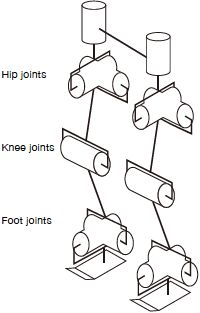
I’m afraid you’ve misunderstood ASIMO’s legs; it uses a weird sort of dual level gimbal thing. I’ve went and collected some clearer references that show the internal structure; this one is from Honda’s own website (albeit a bit diagramattic)
While this image from someone else’s attempt to recreate the robot’s leg is probably the best interpolation of what ASIMO’s internal structure looks like.
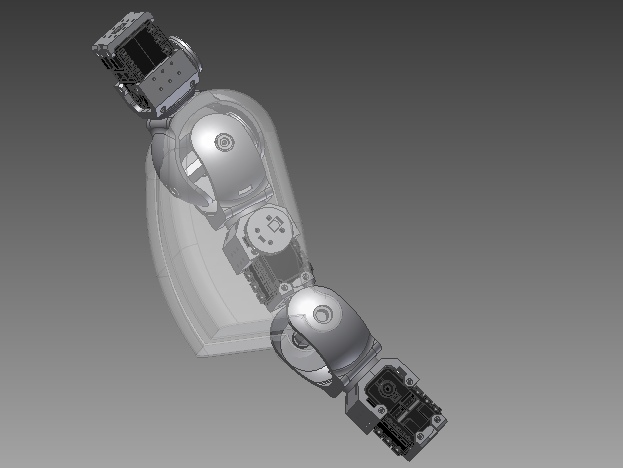
ASIMO’s a pretty tricky guy since most of its actual mechanism is internal but take a look at a few more pictures and you’ll start seeing how its parts work. Good luck!
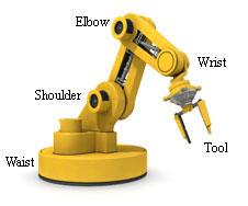
Hi @Lostscience, I have been looking around for something that could be useful for you, and found this little diagram.
Industrial robot arms a part of the basics in robotics, a good thing to start modelling would be something like this, once you have mastered the basics then the rest will follow naturally.
Okay, thankyou solarforge.
I am modeling the robot arm and here is what i have so far.But how do i correct my mistake?I need a hot key or something.
Here is an industrial robot arm that I made today, as you can see the image of the robot arm that I previously posted helped me a lot…
Hope this brings you some inspiration.
Industrial_Robot_Arm_v1.1.blend (744 KB)
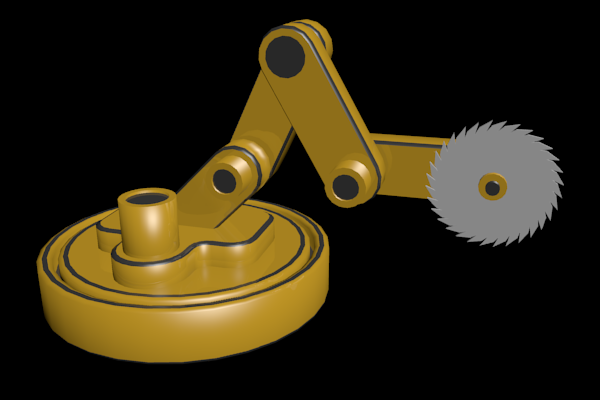
What method did you use to model it in blender?That is what I need to know.Could you please describe it or make a youtube video?
Ah ha ! the spin tool is what I intensively used to make the robot arm pieces ! I don’t know what I would do with out it ; Well I do, I would have to do it manually !
The beauty of arraying : http://wiki.blender.org/index.php/Doc:2.6/Manual/Modeling/Meshes/Editing/Duplicating/Spin
