Hello,
I wanted to create a crusader helmet (to maybe 3d print), but I just don’t know how and where to start.
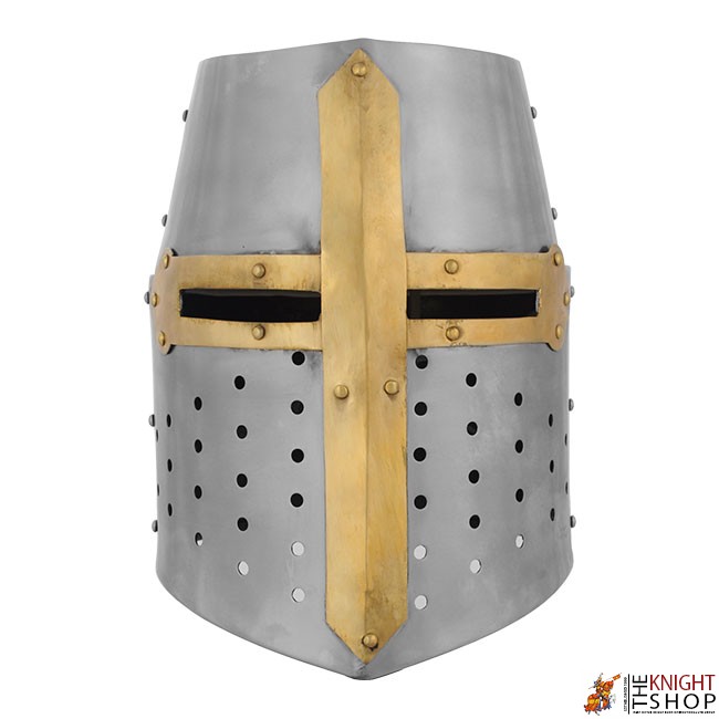
This is what I (roughly) wanted to recreate:
Google Search
First of all, I don’t know with what base mesh I should start.
Also I don’t know how to get it to look smooth but still have hard edges like realistic metal should have.
Lastly, how would I make the holes for the eyes and mouth. Because i’m pretty sure boolean isnt going to do the job.
Thanks in advance,
-LeSpook
If you are a beginner this is probably not the best model to start with. Getting round holes into cylinder and making it look good is not trivial.
However, if it is for a 3d print you don´t need a clean surface so there is really no reason not to use boolean.
Anyway, if you still want to model it without booleans:
I´d start by modelling a hole. Round holes are inverted cylinders. You only need one side of the cylinder so create a circle with few - perhaps 8 - segments and arange two of them above each other. Then connect the two holes so that you have a strip of two holes at the end. Duplicate and connect your holes until you have a strip of holes that is long enough.
After that duplicate the strip and arange hole strips around a cylinder the size of the helmet.
The eye holes you simply model into the helmet by deleting a couple of polygons.
You get a smooth but hard edge look by using Subdivision Surface modelling and a lot of supporting loops.
After getting all that done you use a solidify modifier to give the mesh thickness.
Hi,
Thanks for responding.
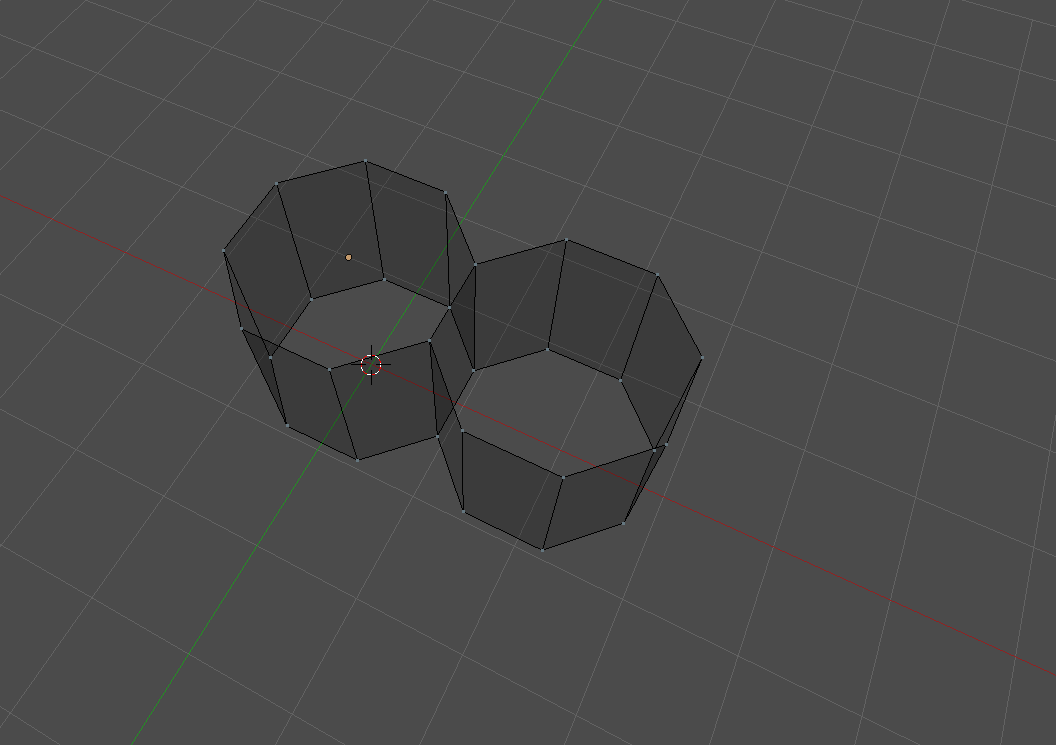
I just wanted to know what you exactly mean with the holes.
So I made two circles and connected them, duplicated that en connected that to it.
I took a screenshot:
Not quite. Create it 2D first. You add the third dimension later.
Make a circle.
Duplicate it and move it above the first one.
connect the lower edges of the upper circle to the upper edges of the lower circle.
Then copy the whole thing and connect the open edges again.
i have experience with 3D printing, and i can definetely say that this will be extremely difficult for you. Because of the size of the print. You need to split it up, and you need a good understanding of what results you will get out of the printer to know how to slice things properly.
Try something simpler as your first print project.
Excuse me if I don’t understand.
Why would this be so difficult?
I can just export as .stl and slice it in cura where I could also scale it down.
I know my printer can handle these sort of overhangs and small details very well.
Oh well I might not have been very clear about that, I intend to use it a small statue of some sort.
So that would be about as big as a ping pong ball.
that will cause other problems, like the thickness of the helmet. Ideally you dont want it to be less than 2-3mm in thickness or else it’ll just be flimsy.
You also wont get the holes with that scale, you would have to add solid cylinders where you want the holes and drill them afterwards. Same goes for the eyes.
Well thanks for the help, but my primary concern is actually modelling it.
If i’m going to print it I might have to change the model, but then I would first need a model.
Yes, bevel is availaible in 2.79b. Standard shortcut should be CTRL+B but you might want to look it up directly in EDIT mode: Mesh -> Edges -> Bevel.
Anyways, I just tried and it seems to work a little differently. In 2.8 a cutout in a flat plane/grid can be bevel’d (by pressing V) but in 2.79b you need to extrude the grid around the cutout and then bevel the resulting inner corners.
Btw, should you aim for a helmet to wear, I really thought you were, try a Spangenhelm type helmet. They were worn in that period, too, but made from smaller parts which a printer should be able to deal with.
Well, I don’t have the printer yet actually. I was going to buy it soon because my old printer does big suck.
And yes i’m confident that it can handle the helmet (its an ender 3).
Besides, in the model you sent me, I think the holes would actually be too small for it to be print out wouldn’t you say?
Anyway, i’m just going to try and model it for the sake of learning to model a cilinder with holes.
When I print it i’ll ask if I can’t get it to work.
Thanks anyway!
Edit: I just looked at the topology, how did you even make that? I don’t see any sign of a boolean modifier and the verts on the holes aren’t even connected to the model. How do you do?
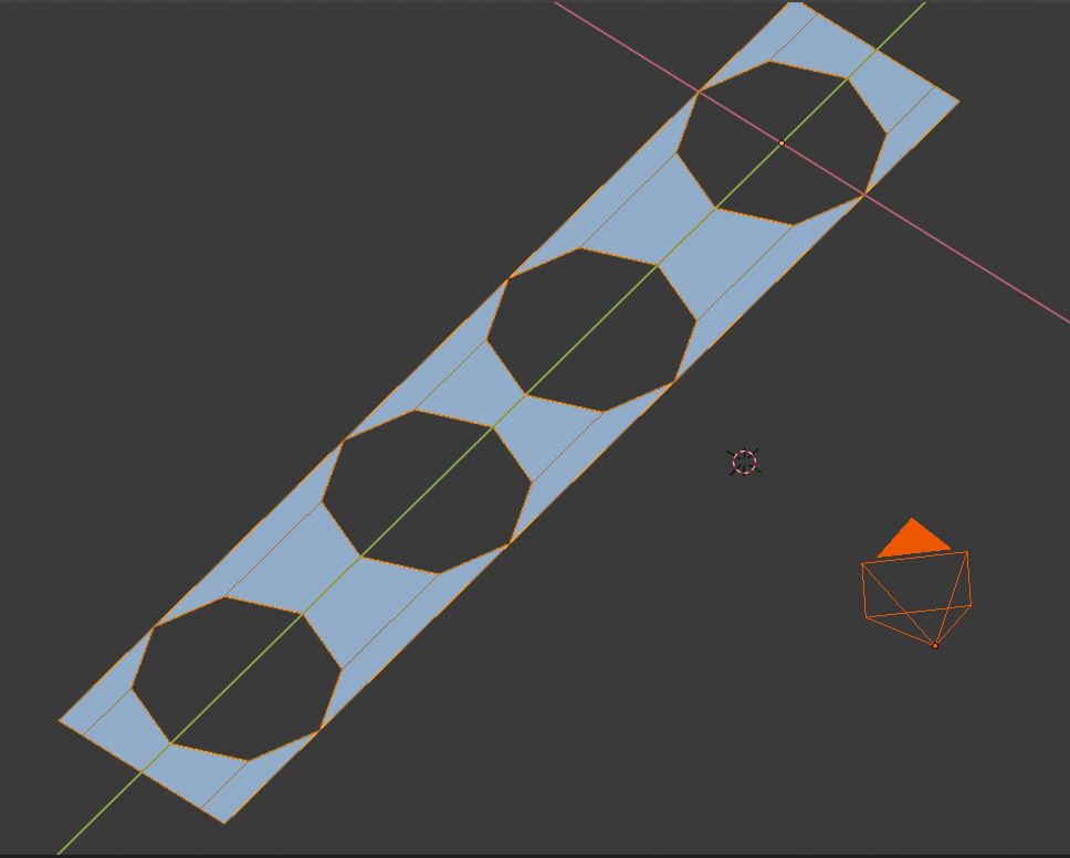
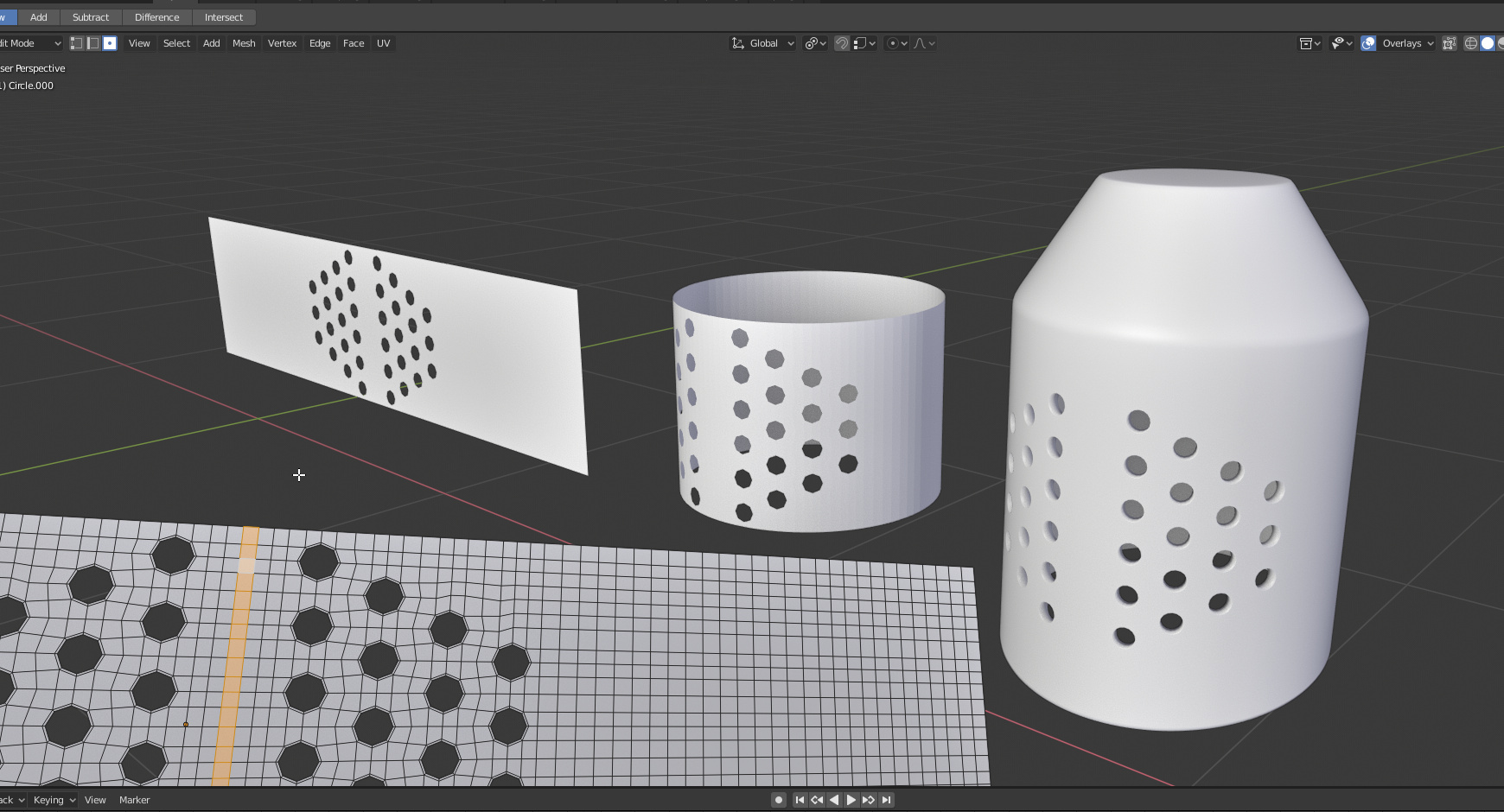
I would follow @Lumpengnom’s advice an model the section to have holes flat. You can see that in this example. Start with the circular holes. Use extrude and scale to give them all a ring of faces. Join them all up. Extend the pattern out equally on either side. Make sure the object origin is in the centre. Use the Simple Deform modifier set to Bend and 360 degrees. Apply that and then model the rest of the helmet from that point. Obviously you can then add a Solidify modifier and a Subdivision one too.
non destructive booleans. They’re not even applied.
And yes, the holes wont even show up at all on a pingpongball sized helmet. And you will also run into a problem with the general thickness of the helm, and the metal plate things will be impossible to print, as they will warp. However, printing them all as one piece wont look nice at all.
My point is, this is a very difficult model to print properly, i strongly suggest you pick another project as your first, just to get familiar with the printer, and learn how to deal with the problems you will eventually run into.
If you want to model the helm just to model it, thats fine, i’ll gladly help you with that. But dont expect to print it any time soon.
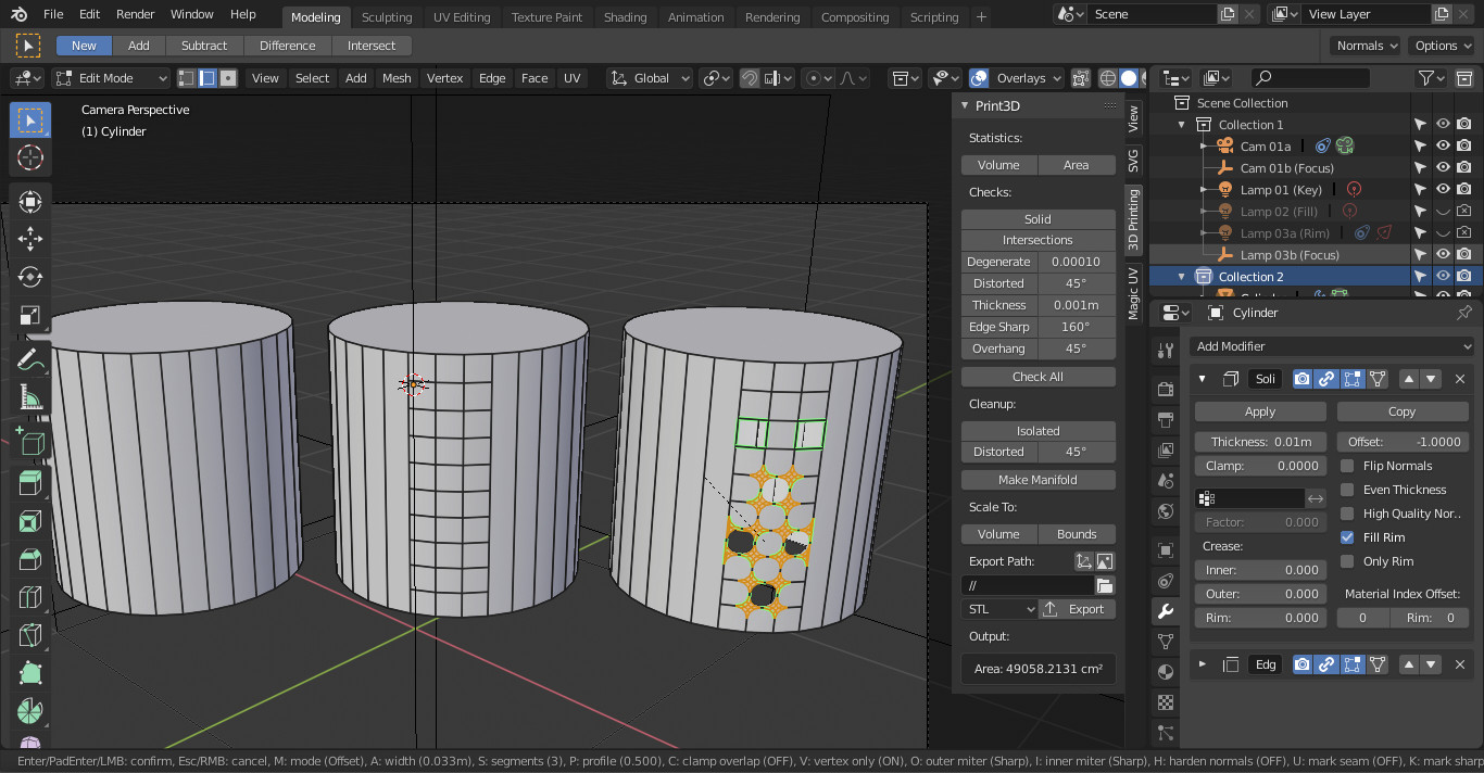
After more playing about with the Simple Deform modifier. You can do it fairly exactly rather than the first time I tried this. If you know the desired dimensions of the part of the helmet with the holes in (the part with straight rather than taper sides), just multiply the diameter of this section by Pi. That will give you the radius which will be your required width for the rectangle that will finally be bent using Simple Deform. Then its just a case of subdividing that rectangle as much as you require. I deleted 2x2 face segments, using LoopTools Circle command on each of the resulting holes, then with Individual Origins turned on I extruded these and scaled them inwards to the desired hole size. These holes would probably need an extra edge loop added in to tighter up the edge of the hole for Subdivision Surface. The “crease” at the back wouold disappear after applying Simple Deform and removing double vertices.
Just remembered that the very first thing I ever 3d printed was a helmet It was a Blender model that I sculpted of one of my pencil drawings and retopologised. I didn’t even own a 3d printer, not did I know much about it. There was a place called MakLab in Glasgow that allowed people to drop in and use their 3d printers for a fee. Sadly closed down now. I only got as far as printing the helmet, which took several failed prints until I worked out the best orientation for it as it’s a weird shape. I may revisit something like this now that I have several 3d printers of my own.