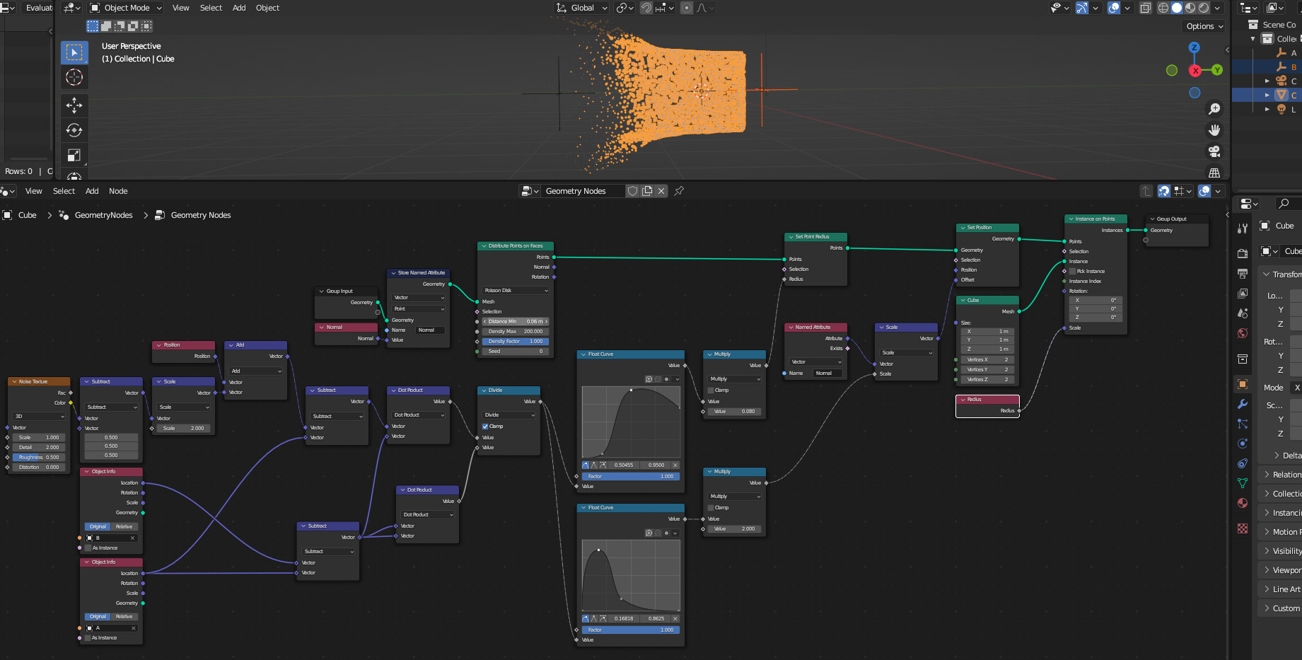
Hello, I have been trying to follow this tutorial. I have had to figure out how this process works in Blender 3.3, as all of the attribute nodes have been put out of commission. However, at the specific point in the link where the tutor goes over using a noise texture for offset (displacement) on the trailing edge, I lose my way.
The main problem: I cannot get the Dot Product vectors (controlled by the two empty spheres shown in the screenshot below) to control the noise texture displacing only the trailing edge, not the whole geometry.
In another project I had similar issues with not being able to use geometry nodes to create vector co-ordinates along any one specific axis. For instance, combining or separating XYZ along a gradient doesn’t do anything, as you might do for a gradient in a shader setup. Unsure if that is related or a separate problem.
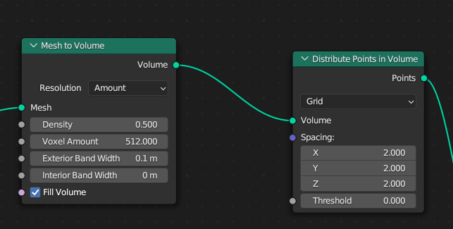
Blender 3.4 released with a few new nodes, one of which caught my attention: ‘Distribute Points in Volume’. So we can have this same effect but it fills the whole object as a volume and not just the outline/shell of the geometry. I had been trying to figure out doing this with volume for a while, perhaps by using cell fracture to generate points within the outer boundary, but they went and added this new node, nice.
This is quite processor intensive; changing the distribution type from Random to Grid crashes Blender for me, as does increasing the density too much, although I imagine this depends on how high-poly your geometry is.
As I can’t have it mega dense, I will need to find a more creative way to have the final solid geometry reveal. Perhaps combining it with the original effect or layering it up with a more simple animated mask.
Any suggestions from anyone would be welcome, open to ideas
Note: I am sort of using this thread as a journal for this experiment, please someone let me know if that is not appropriate and I’ll make a new thread elsewhere.
Renders of the above solution, I’m not sure what is causing the warbling of the instances on the points, it isn’t the W factor in the noise texture. It’s present on both the outer points and volume parts but it is definitely stronger in the volume, so I’m not sure.
It may not matter as I combine this with a masked blend of the solid head render.
Edit: Upon reading the Blender manual on the new node it looks like having the method set to random as opposed to grid is the cause:
Random: This method creates a distribution that is not stable as the input volume deforms.
If I can get the grid method to not crash Blender then I will test this theory.
I got the grid method to work without Blender crashing, you effectively have to use the spacing function to set density. It was crashing before because stupidly I have this model at 130m wide, so the spacing being set to its default 0.3, 0.3, 0.3 was making it incredibly dense, just like me, oops. Density on the Mesh to Volume node doesn’t really do anything (correct me if I’m wrong someone please).
Big issue with this is that we can clearly see the grid even at quite high density, so random it is. There is also a moiré effect going on, don’t want that obviously.
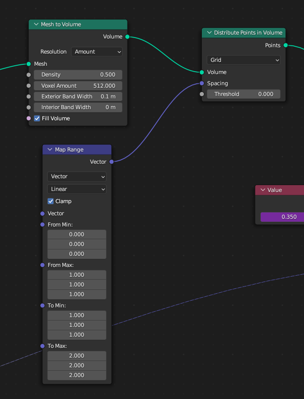
How would you do it? I attempted to do something quickly by adding a vector map range node to the spacing, but I think the points are always going to conform to the grid, otherwise you would use the random method instead of grid.
I’m hoping future updates to this node may stabilize the random method.
Careful:
…that’s not a field input - it’s a constant input - i.e. just 1 value for the whole network. Field inputs are diamond shaped - you wanna be using those instead (for variation).
@Hadriscus 's suggestion is done with a Random Value node plugged into the Offset input of a Set Position node. Also, be aware of the ranges of the values you’re using - e.g. if you’re using any Texture node, the values will be in the range 0 to 1, so you want to always subtract 0.5 to get it into the -0.5 to 0.5 range, which will result in even offsets and not your lob-sided offsets.
@Hadriscus 's suggestion is done with a Random Value node plugged into the Offset input of a Set Position node. Also, be aware of the ranges of the values you’re using - e.g. if you’re using any Texture node, the values will be in the range 0 to 1, so you want to always subtract 0.5 to get it into the -0.5 to 0.5 range, which will result in even offsets and not your lob-sided offsets.
I did give this a go, but couldn’t get it to work. Changing the values to min -1 to max +1 has worked better, thank you both
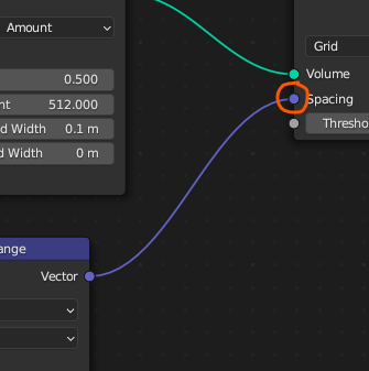
I am still getting my head around the concept of fields, so when the vector map range into the spacing attribute showed some change, I just went with it. I don’t quite understand the what you’ve said here and how that adds up:
that’s not a field input - it’s a constant input - i.e. just 1 value for the whole network. Field inputs are diamond shaped - you wanna be using those instead (for variation).
I say this because the vector map range output is a field (correct?) but the spacing input is a solid purple dot, and I cannot find anything in the Blender manual describing what that means as an input type. You say it is a constant, 1 value, but it has 3 values presumably for each axis? Sorry if I am being a bit thick.
Nevertheless, using an offset with random value has worked. I will render out an animation and see if the warbling of the points has been solved, fingers crossed.
Fields and single values are unrelated to the data type (here a vector with three components, as you pointed out). A field means every vertex in your mesh (or every voxel in your volume, or every control point in your curve) has its own value. The position input is a field because every vertex has its own position. The random value node also outputs a field, which means that it generates a different random value for each element in your mesh and can be used to scramble your point cloud.
A single value on the other hand, means a single value is passed to your entire mesh. Take the transform node : it takes only single values, so if you pass it 3.5, then all your mesh’s vertices will move by 3.5 units.
Thank you @Hadriscus, that explanation was very helpful. I realize now that the vector math node was being used in the spacing input, but it was basically taking just the to min value by the looks of if. So now I just input the values.
Some development:
The moiré grid effect lessens as density is increased (spacing values decrease). If I try the advised set position offset, it is effectively identical to using the random method, we get the warbling of points. So unless there is a way of each point becoming stationary once in it’s final position the best option is to increase density/decrease spacing for the grid method.
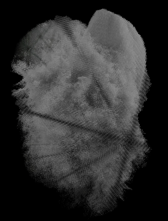
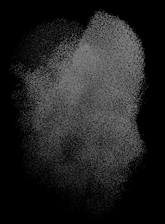
If I try to decrease the spacing any further then Blender just crashes. If I am lucky I can render 1 frame at 0.5/0.5/0.5, and it looks like this:
Which is closer to the level of detail I want, but I will have to compromise and use 0.75/0.75/0.75 with the camera further away for my final animation. Maybe I will use smaller close up parts for more macro detail then edit the different cuts together.
If I try and combine (join geometry) with the original effect from further up this thread, Blender crashes again. It looks like this for a reminder:
I can’t decide which I actually prefer in all honesty. If I could render both and offset the timing for the volume version to come in later, that would look cool.
I’m not sure I understand this. The points don’t stay stationary ? if they’re still affected by the noise texture you should be able to just multiply and animate it down to zero once the points have reached their final position.
You have the original mesh, right ? Why not fade it in gradually as the points move into their final position ?
The points don’t stay stationary ? if they’re still affected by the noise texture you should be able to just multiply and animate it down to zero once the points have reached their final position.
No they don’t it looks identical to the random method with the warbling. I may circle back to this but for now I have a solution I’m happy with. Thank you for your help
You have the original mesh, right ? Why not fade it in gradually as the points move into their final position ?
This was the plan, I just wanted to do it in Blender, which I’m unsure how to do with geometry nodes. I tried and failed to capture attribute the noise textures in the geo node setup to use in a shader setup. I have conceded and just used a basic mask in After Effects, but I am happy with the result:
Going to comp it into a scene (hence the moody lighting) and add extra shots but this is the effect in it’s entirety.


