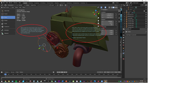
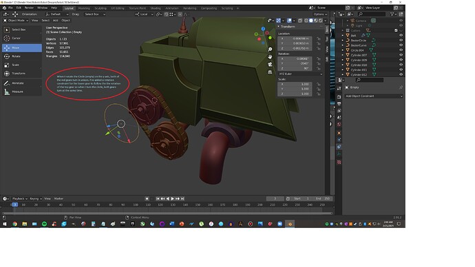
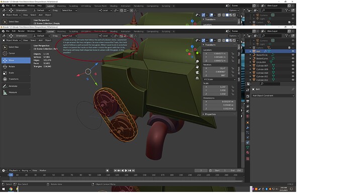
Please see attached images to understand my problem…
I wasn’t able to add two screenshots before cause my level wasn’t high enough… now it is…
These two screenshots may help you…
Hey, You have to ‘parent’ the ‘curve’, ‘mesh’ (arrayed object), ‘Empty’, and Hubs(wheels) all to the same Parent - that way when its transformed(indirectly), everything will still maintain its correct location. Make sure all rotations are cleared/applied first.
The empty you use to rotate the hub could be eliminated if the hubs ‘origin point’ is properly placed - then you could use its local rotation to drive the ‘tracks’ “X” location or the other way around.
Thanks for responding! I’ll give it a go…
Yeah not sure what I should make the parent and in what order all the children should be in… What I’ve got now is setting the 3d cursor to the top hub and I’ve made sure to apply rotation to the hubs prior.
I’ve got the origin set to the 3d cursor so I can spin the hub around the x axis. I know no other way to get the bottom hub to spin at the same rate as the top hub other than to use a “copy rotation constraint” to the top hub. Now when i rotate the X axis, the hubs spin together at the same rate.
My belt’s array hasn’t been applied so I’m still unsure what to do…
I think ajcdfin is answering, how to keep the entire structure moving as one (which is to have the curve, track, and both wheels all parented to an identical object.)
But I think you might be asking, how to move the track about the curve, so that when the wheels rotate, the track moves appropriately.
The way to do that is with a driver on the location of the track, so that your control empty’s rotation turns into track translation. (Not a constraint, because constraints are only ever going to see rotation in the -180, 180 range, so they’ll jump when you cross that boundary.)
To figure out the math for how much your track should move, you need to know the length of your curve. I do that by making a quick, simply subdivided unit length mesh with a curve modifier targeting the curve, then scaling it until it stretches from beginning to end. If the mesh is 1 unit long to begin with, the scale I end up with is the length of the curve.
Looks like I’ll need to research into “drivers” I’m a newb at this kind of stuff… Up until now, I’ve only used blender for modeling and have only done some simple animations using keyframes. Thank you for responding!
Drivers are pretty cool, and not really all that hard.
Quick start, with some assumption about your setup: Right click in empty’s X rotation field (like in the sidebar) and “Copy as driver”. Right click in track object’s X location field and “Paste as driver”. Open a driver editor viewport, with your track object selected, and select the driver from the list. Open the sidebar in the driver editor and switch to driver tab. Change from “averaged value” to “scripted expression”. Edit the expression field. I think that should get you started a lot faster than hunting through Youtube videos.
Thanks for all your help… I’ll try this.
I followed along until you mention editing the expression field… I’m guessing you mean the context box or window with the word, “expression” over it. In the little box, it says, “rotation_euler”. I have no idea what that means… euler… is that like bueller? do I write something in this box??
It’s a variable name. What that variable means is defined by what exists below that, just below the “add input variable” button. If you’ve followed the steps I mentioned, then what it is is the keyframed (not constrained) X rotation field of the control empty, measured in radians. You can see what this value actually evaluates to by looking at the “driver value” part of the sidebar if you want.


