Perhaps that can somehow be combined with geometry nodes?
The other parts I should be able to figure out myself because I achieved them in independent tests at least once years ago: image color defines height, image color deletes instance points
I’m using the UV output of the grid to drive the image sampler’s vector input and the viewer node is set to face mode to show that you should be capturing face colors for the shader.
The triangulate-dual method creates skewed hexagons. If you are going to make regular hexagons it gets more involved but in the end you basically need to generate the UVs (X and Y coords in the range 0 to 1) from the face positions if you want to get the full dimensions of the image.
I copied your node network and yes the hexagons are too skewed for my needs.
How can I get the instanced hexagon meshes to take on the color of the corresponding area of the texture (and also use the texture color to influence height offset/scale, and visibility)?
Would anyone be willing to explain to me in minute detail exactly what it does? Like minute-minute detail suitable for an illiterate and innumerate dummy?
What does the combination of positionbounding box and map range do?
Is there a terminology for that? I ask because it reminds me of something similar I’ve seen done (see instagram link in first post) and I wonder if it’s the same technique or something different and if it has a common name.
Why is realize instances necessary?
Why does the image texture have to be in geometry nodes and not just over in material nodes?
How do you actually get the colors from the image to be accessible to the base color in the material so it can be rendered in Cycles?
Position is the position of some domain… in this case is the face domain, so it would be the position of some face. It can be anywhere in the scene - in this case the Geometry it is being evaluated against are the hexes. Bounding Box gives the maximum and minimum positions of a Geometry - in this case it is the Geometry we generated the hexes from so it gives the range that the hex face positions would be in. Map Range will linearly transform some value (the position in this case) between some minimum and maximum to be between some other minimum and maximum. e.g. a Float Map Range which has From Min-1 and From Max1 and To Max0 and To Max1 will transform the input value 0 (which is half-way between -1 and 1) to 0.5 (which is half way between 0 and 1). So, effectively what that bit of the network does, is it maps the face positions from their object coordinates to the UV coordinates → Bounding BoxMin and Max to (0,0,0)Min and (1,1,1)Max. Since UV is 2D, the z coordinate doesn’t effect the image sampling.
Depends on the use-case… could be range mapping or a coordinate transform.
Its not. See my 2nd example in my previous post. “Instancer” attribute type is used in the material editor there.
It doesn’t have to be. You can save the mapped coordinates and use them as texture coordinates in the material editor.
See my last example. It uses the Attribute nodes to expose the color, but like I mentioned here it could be exposing coordinates also - Blender is very flexible.
I guess I don’t fully comprehend coordinates and how vector inputs are used I guess. I’ve done several javascript tutorials and khan academy videos explaining vectors and vector math and they’ve not helped me understand what is going on in blender at all.
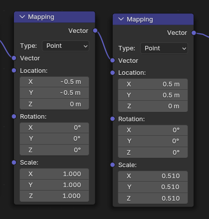
I really wish I understood simple things like why this works for scaling UVs from the center instead of the lower left corner:
I’ve been doing my testing in a different project. I’m going to start over. First thing I need to do is understand how you setup the math for
Plane Size(in m) and Grid Size(in pixels).
because it is most convenient to have the “pixel” object instances auto-scale as the grid size increases while the plane size remains the same.
Then I want to try the instancer attribute type without realize instances. In my initial test I did get some colors from the image to appear but they did not form the image. I think if I just start over from scratch I’ll avoid whatever is breaking it.
You can save the mapped coordinates and use them as texture coordinates in the material editor.
I was able to get this to work. I’m guessing in the end I will either go this route or the instancer option without need for realize instances. Don’t actually know which or why, just want to get all the options you’ve described working to see if I can actually get them working.
Its because of order of operations. The material Mapping node performs Scaling, then Rotation, and finally the Translate (Location) operations.
So breaking it up into all the parts this is what is happening:
Translate by (-0.5,-0.5)
Scale by (0.51,0.51)
Translate back by (0.5,0.5)
i.e. the pair of translations are setting a “pivot point” for the middle operation. Same technique works for rotating about a point, just replace the middle step with rotation.