I tried using a simple deform and a bezier curve, but none have worked out.
I also tried different things in Edit Mode like connecting the vertices at the sharp angle and dissolving, merging, deleting, nothing seems to work.
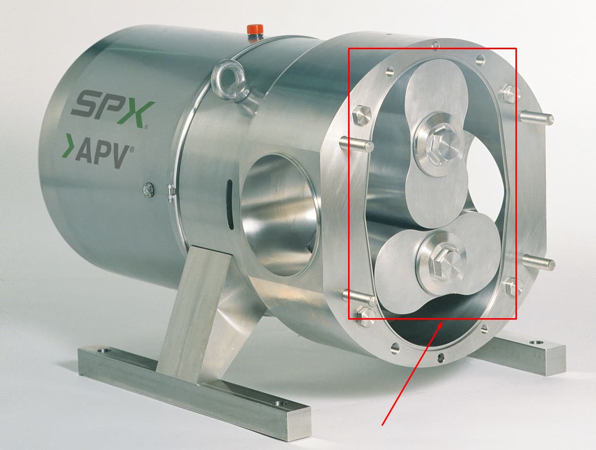
I’d really appreciate some help creating the shapes of those rotary lobe pumps.
Here’s a video I found (done in Fusion 360) that may better show you what I need. I need to do that, but in Blender, and I wanna start with the rotary lobes: https://youtu.be/NV3sVYXc-p8?t=165
The very final scope of this part of the project is to 3D-print a pump that will actually be used to pump water continuously (long-term)
I wouldn’t say it needs to be 100% accurate right now, as long as it serves its purpose effectively. Your method will work well for the design, and probably for a 3D-printed model (model = prototype for testing)
However down the line I’d want to 3D-print a model (model = precise, practical device for real-life application), and I am curious if there are tools in Blender to do it mathematically precise.
I think I might have found something (this reply took hours to write as I was digging through Blender)
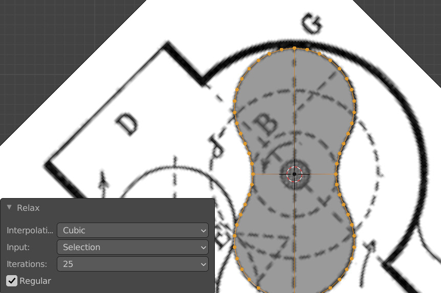
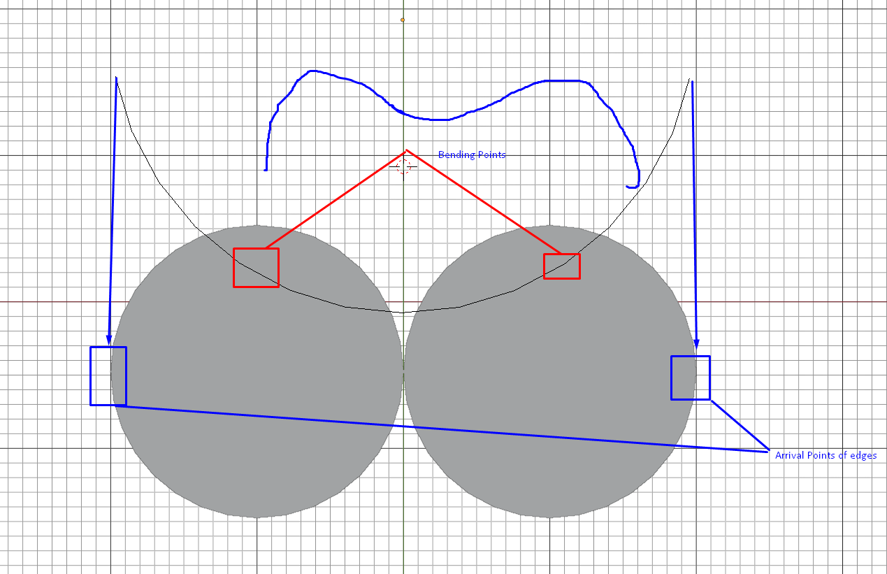
If I create a cylinder double the size of the two cylinders needed, then separate half of the edge of the big cylinder (so I’d get a semi-circle) and then add 2 bending points a third of the way from the edges, and bend the edges the other way around, perhaps using a bezier curve, I’d have half of the shape of the lobe, then perhaps mirror and extrude.
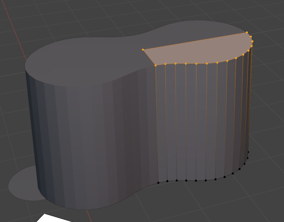
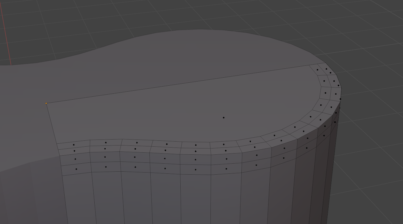
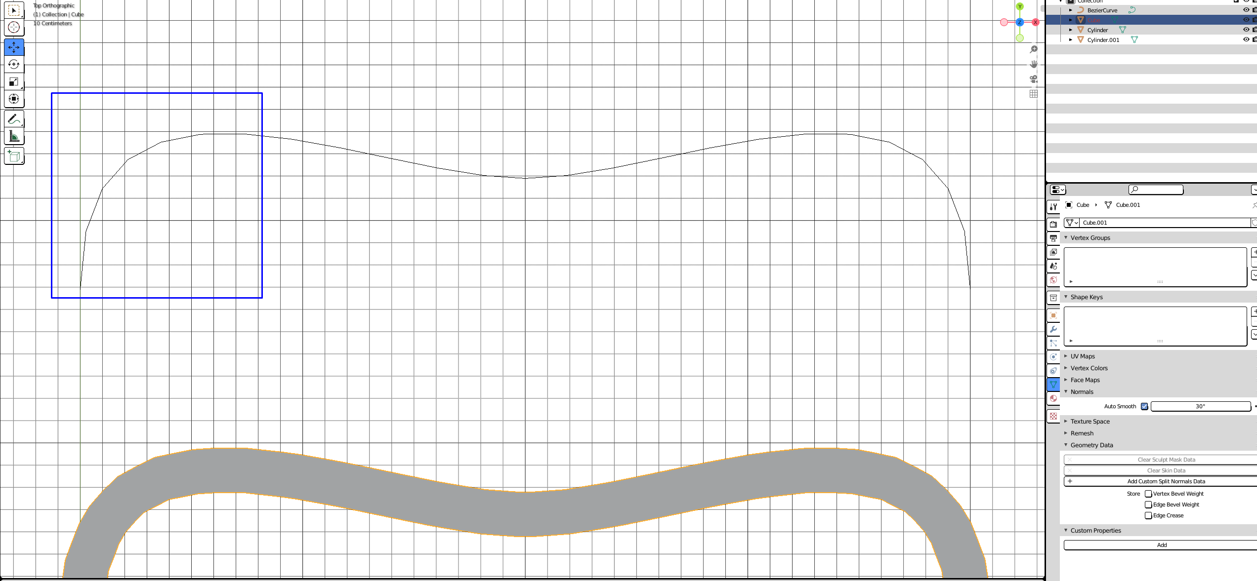
I created a 3-point bezier curve shaped as half a rotary lobe, then I created a cube and transformed into a shape similar to a wall, and following a youtube tutorial moved the mesh through the bezier curve and then applied a mirror modifier.
I found the settings to increase the number of subdivisions on the curve.
I’m gonna try to figure out now how to get the right length and mesh shape to pass through the curve, and then how to cover the holes and solidify the whole shape.
I want to thank you again for the help, even though this path is different from the one you responded with, the idea came to me after your response.
I hope I can figure out the rest, else I may post another reply here or start a separate thread.
Are there any options for designing in Blender, then transferring the project to Fusion360 for refinement before 3D-printing?
I’ve tried my hands in AutoCAD, Fusion360, FreeCAD and Blender (oh, and Shapr3D)
Blender seems to be easier to learn, but the main problem is that AutoCAD costs money I don’t have, and my laptop is too slow to run Fusion360. It’s very slow.
(I don’t contradict, just providing context why I ultimately stayed with Blender)
But I am interested if I could print at least a functinoal model that would work effectively enough to show someone that it works.
Or do you think, despite Fusion360 being slow on my PC - it’s still better to learn that one and deal with the slowness?
This kind of pump design is going to have problems with sealing the straight surfaces and the bearing. Is there a reason not to use some existing factory made water pump and just maybe 3D print some mounting hardware if needed?
Is there a pump design that is more suitable for 3D-printing, from the perspective of efficiency?
the pump is part of a bigger, custom project. This project is also flexible in that such a product does not yet exist, I have nothing to go off of, I’m still working out its details and measurements, and even if I create an MVP protoype I may later need to adjust its size. So instead of trying to find pumps for sale and trying to match the pump’s design, components, size and capacity to the rest of the project, then if I later need to create a bigger or smaller project have to find and buy a new one, I figured I’d just 3D-print all the components so it gives me control over their sizes and capacity. More importantly, I figured I’ll probably never find a manufactured pump, the design of which matches my project (the pump would be connected to another, custom component).
For bearings I figured I could buy them, and perhaps use some sort of resin or glue on connecting points to help with sealing, though not perfect - I’d find a better solution down the line.
Once I have a working protoype that is effective and practical, and I have all the correct sizes, measurements, design (CAD/animation/2D Drawings) - then perhaps I could either find another, more precise 3D-printing solution, or find various manufacturing companies to manufacture the components according to my design. But I need at least a prototype first, and it does need to be precisely customized.
The nerfed/downgraded license is free, as I understood, for a one-year period. However the simulation functionality is all removed. I imagine I’m gonna make the design in F360 with the free license, and when it’s about done in terms of size/design - I’d buy their cheapest license to be able to run simulations before 3D-printing, to check for any errors.
As far as I know, you usually first design the overall system, then compute or estimate the volume and pressure your pump must be able to output and then select the pump design according to available power source and rpm range.
You also have to consider how clean liquid you actually have. The design shown above is vulnerable to any small particles in the flow.
For example, typical washing machine water pump uses very simple propeller with loose tolerances and enough rpm and power (typically 30-45 W) because the pumped water is not filtered.
If you need to optimize for volume, pressure or low power requirements, the design will be different. After you know which design you need, you can then consider which practical design is easiest to print.

