I’m trying to replicate this type of effect. facebook.com/groups/1626784907645458/posts/3293839510939981/ So Do you think you could use this type of Geometry nodes to replicate a laser blast on an object as seen at 3.10 of the video of ako?
I’ve watched several tutorials and I’m convinced that geometry nodes can do this. https://www.youtube.com/watch?v=rF-ZSxUKpf8 This might be good for making the hull deform. https://youtu.be/QA13LPCZ3dM This might be good for replacing the hull with debris parts. https://www.youtube.com/watch?v=keKDABQfxQU This might be good for creating the blast radius. Although in my tests the you can’t use scale instance node but the scale elements node since 3.1.2 version of blender. I’m not sure how to replicate the transform node he used in the tutorial, seems to transform the whole collection now.
https://youtu.be/xKiv6dKupoE Maybe This Tutorial should of been the first link, but having layers underneath is key to the effect I’m sure. Maybe a cel fractured lattice structure as one layer for structural Debris. Or building a lattice or some sort of structure based on primative geometry, based on the size of the original mesh, and using that rotation tutorial based on a empty.
Well, I’ll be watching these tutorials and seeing if I can puzzle this effect out of geo nodes. If anyone want’s do help. I’ll be using This Fighter, which is similar to the one in the ako shot.
But any fighter jet would do.
A thought is to Have a debris object under the main shape mesh. and have that scale and deform using an empty? It may be possible to construct underlying structure using geometry nodes also, like simple wiremesh with solidify? Those are not Geometry nodes yet. (maybe everything nodes one day) Maybe have the same empty make a Hole in the mesh. Or parent the empty to a cylinder object that would be the laser blast and scale that in one axis. Then the laser blast effect would be automatic.
Lastly would be of course the explosion.
I’m not that good with geometry nodes yet, would be awesome for space battles scenes.
Yea this is pretty complex what’s happening to that ship.
1.What are you looking for in terms of quality? is this your money shot? or do you want something that “just does the job”?
2.For how long will it show? is it only once for a fraction of a second (as in your link), or are you looking for a generic solution that you can apply to several ships and shots?
3.What kind of style are you going for? it’ll factor in the decision
Depending on the details I could consider doing it by hand : model a split hull, animate it using shapekeys could be cheaper than engineering a complex geonodes-based solution that works in every situation, on all sorts of surfaces, etc. not to mention geonodes doesn’t have anything in terms of destruction/splitting of meshes or physics solvers so far, this means the explosions and destruction itself cannot be made there.
But if you’re going for something very stylish where suspension of disbelief is not a concern, sure you could make something out of a boolean and a bulging surface with debris spawning on the nearing surfaces. I’m not sure there is a way to feed that to Mantaflow, maybe through an attribute but I’m really not sure.
You can get away with animated debris and sparks in geonodes by instancing stuff on a point cloud and animating the points, but that’s not physics-based so it is kind of limited.
I was thinking about option 2, making something that would be used generically on any surface. And probably for only 3 to 4 sec long so not so accurate probably is ok. Thanks for your Ideas. I didn’t consider using physics simulation.
Ok so you’re okay with spending some time getting a generic setup working. Yes, you can probably get something with geometry nodes even without solvers, but that’ll take some dissecting what the effect is composed of exactly -there’s quite a few different parts to it. The bulging thing is not too difficult, it’s when the surface rips aparts that I’m not sure how to approach. Maybe you could define a “ripping line” along the mesh (defined by the boolean cutting through it) and instance “metal sheets” along it that curve/deform as the object passes through. I thing that’s how I would start, but only trying will tell whether it’s a good approach.
You can do it like this (hope I understood you right)
That was a really good thought process of how to tackle this, very concise. I’m not sure if i should use an object info node with some structural stuff I model, (Which means I would model it for a specific area of the ship to be destroyed, Like right behind the cockpit like in the Ako video) or make generic substructure parts using geometry nodes.
If I try to add models and then use the object info node then in geometry nodes this tutorial shows a complicated node setup for making Electric poles and using the switch node to toggle which type of pole to select. (he had several types) This bit of node tree magic Could be used to use for different sub structures for different parts that are exposed. I.e. switching to a substructure of an engine if the blast hits the back of the spaceship.
Exposed parameters would determine the depth of the sub substructure I’m thinking.
If successful we could destroy a fleet of space fighters with nothing more than a space fighter Object and a null and a geometry node modifier just like in the Ako Video.
In edit mode there is a function called sperate by parts or material. Does anyone know if that might become a geometry node?
This tutorial might be good also for the bulging effect. So the dual mesh tutorial blows out the glass canopy, and this one animates it repulsing. I’m like going to have to do these tutorials several times to understand them and combine them to this effect I’m trying to achieve. So I’m thinking that there will be two geometry nodes modifiers, one for the glass canopy destruction, and one for the hull destruction.
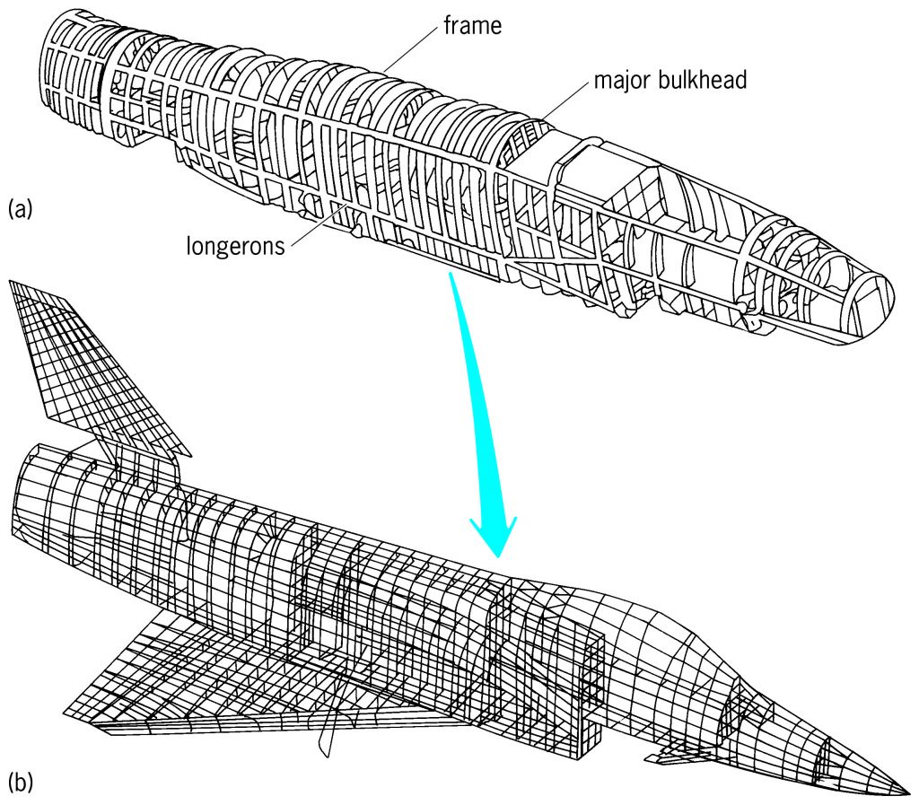
So this image of an airframe might be done with the boolean node. How to make this in geometry nodes will be important in using this for whatever fighter you would use. I will experiment with boolean using rectangles and instancing them into a grid to make the airframe, and with bolts. Then figure out how to make the perpendicular parts. And although a wireframe might be enough, I think using a profile curve might be better. I think I saw a tutorial on how to make a profile for the curve, in the bevel modifier?
Ok this tutorial has reverse bolts, but I’m sure I can make bolts using some of what I saw here. And He uses the extrude mesh which I think will be helpful. Sort of like a solidify node in the modifiers.
So one thing I have no idea about is how to constrain this bolt like effect to certain parts of a mesh
In the video he uses a greater than node to constrain the bevel angle.
Yes! There’s no case node but simply by stringing several switches end to end you can define as many parts as you like, and then it’s just a matter of painting over your model to define them.
This is such a good idea, using dual mesh to create fracture,… Dual mesh is in 3.2, I think it should be released this week if the release planning goes smooth. What it does is it places a face in each point of the original geometry. Then it’s a matter of splitting those faces and transforming them individually…
You can do pretty much anything with a handful of low-level nodes, for instance in order to separate by material you’d plug the material index node into a compare node and feed the resulting boolan into a separate geometry node. Now you have two different geometry streams and you can treat them completely differently.
So, in order to generate the substructure from the “skin” (as it is called in the picture you linked), you’d have to make sure the topology lends to it well… OR I guess you could also instance circles vertically, project them along the interior of the skin and lofting them with a profile. Unless you want the substructure to NOT be affected by the explosion? But having it ripped apart by the explosion is more tricky. Making the underlying parts disappear (by deleting the source edges), but having them bend, is probably more involved.
You can do pretty much anything with a handful of low-level nodes, for instance in order to separate by material you’d plug the material index node into a compare node and feed the resulting boolan into a separate geometry node. Now you have two different geometry streams and you can treat them completely differently.
Ok I imported that jet, I didn’t realize it was an stl. Decimated the file and slapped on a texture.
I was able to download the bullet geometry nodes from The MaxEdge tutorial and that person is a genius in terms of understanding Geometry Nodes. Adding empties and positioning them added bullet holes in the mesh. Complete with holes. I watched his tutorial and while very informative and very very well narrated, I realized this person knows geometry nodes in a very advanced way. Maybe he works with houdini? I think I learned more about how to think about using geometry nodes than any other tutorial. He explained how certain node structures plug into the selection of other nodes and that’s the mask. (I kept on asking myself how do you constrain areas in geometry nodes? He explained that concisely) I couldn’t resize the bullet holes using the empties that position them, and I would have to see about poking around his node tree to see if I could expose or add something that would allow an empty to control the size of the bullet hole. He has some parameters that he labeled and there are two many to be useful. Ideally one would want to be able to control the size of the bullets and if possible an animation of his parameters as something that is automatic. LIke a driver
I noticed in this tutorial how how the author uses certain nodes to open the doors. I was thinking this could be used to displace parts of the skin of the airplane. Investigating.
This tutorial shows how to displace volumetrics, but might apply to geometry nodes also. He uses the mapping and length nodes. Similar to the original anime but as a cloud
The breakdown video shows how the internal walls divide up the structure, perhaps you could use a similar process to make bulkheads and decks internally dividing the ship
Wow, that is super impressive. He made all that internal stuff with geometry nodes, just wow. Makes me think that this effect can be done in geometry nodes then. Thanks. I’m very much a noob with geometry nodes. I’m not sure what dot product node does? I’ve seen it used in texture tree setups to detect edges, so that makes sense to use that.
Dot product takes two vectors. Imagine rotating them in space so that they gradually line up (become “colinear”) → then dot product gradually becomes =1. The more they get perpendicular, the more their dot product will approach zero. Unless it’s the opposite? I forgot
So anyway yes they are used to detect grazing angles, which is where we tend to set down contours/silhouettes most of the time : if you take that dot product and remap it with a curve node, drawing a steep sudden step in the middle, you’ll get an outline.
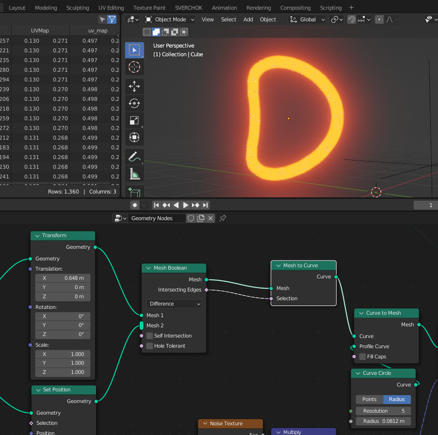
I’ll have to see what I can replicate with your examples. Thanks for your continuing ideas. Very helpful thanks. I’m thinking to make an object like a narrow cube, and use a boolean intersection on it and that would be the shape of the hull. Maybe do a second boolean but smaller on the first boolean, to make it into ring in the shape of the ship. then somehow extrude or thicken it i’ve seen a geometry node that does that. Then redo that I guess node tree along parts of the ship. The idea is it builds an internal skeleton of the ship. That mesh boolean node I think looks promising might be very useful for this part. If successful with this idea, next would be making stringers. Then use the proximity effect idea there to deform the skin of the hull, and the internal skeleton booleaned geometry meshes underneath. The glow at the intersection is awesome if I can get that into the node tree also…
This tutorial shows how to make a node group he names points in mesh, which uses the dot product to delete distributed points outside the mesh. He explains how to use the dot product for this task really well also, and for me the a little of the math what he’s doing helps. If the dot product is negative If he used the less than math vector it would delete all the distributed points inside a mesh.


