How do you recommend that I model the upper part of this train?
It has an odd and awkward shape to it.
How do you recommend that I model the upper part of this train?
It has an odd and awkward shape to it.
It will be helpful if you refer to the video below for how to produce it.
It’s a way to create a rough shape and scale and add details.

I would use a retopology workflow, like what is often used for characters.
Start by getting the shape correct at any cost, without caring for topology. At this stage, you can combine objects with booleans and voxel remesh, you can carve holes anywhere without caring for the topology, use sculpt mode, anything goes.
Once you have the correct shape, then you can retopologize the mesh into something clean. https://www.youtube.com/watch?v=CuQzPDs99yM
After this is done, the last step is to model the small details and mechanical parts as a separate step from the rest.
First off, I would find more images as many as possible, to help in forming those curves… search long enough, and with the right prompts you can find the right images…
I like to use Surfaces to model more organic shapes like this, then once I have them assembled ( I don’t care about anything but shape at this point) I will use a combination of what has already been suggested as well as using Shrink-wrap to form a smooth Quad mesh over needed surfaces and combine that into my workflow…which also includes Lofting Curves
Happy Blending!
These forms are not really that “organic”. I would scale, divide, extrude and move vertices to form the basic forms from a cube, then bevel the edges keeping minimal amount of geometry. It might be necessary to use a boolean operation for the roundness at the front, but it’s only one thing, so manual clean up wouldn’t be that bad. I would consider the topology that I use for the boolean very carefully. I think absolutely the most important trick is to use as little geometry as possible. Then of course adding the detail like all the windows and sticking out parts would get a bit uglier, and I would use separate objects and work their topology in as good as I can manually, or maybe even just create the topology first and extrude stuff which might also just be faster. Personally, I would not use subdivision surface modifier here at all, but subdivide destructively as I progress and clean up all the unneeded edge loops after each subdivision for example, I would definitely need to subdivide before adding windows. I think there would be a fair amount of manual vertex moving and topology creating, which I don’t mind, but I know that might not be for everyone. I still think thinking about topology and creating it manually is the most efficient way. I would leave surface detail for the end and I think I would go with sculpting. I think sculpting would be fastest and most precise way, but then baking to normal/bump maps or decimation would likely be needed, so not sure… Baking is extra time, decimation is less elegant. Depends on the purpose and how detail you wish it to be. Surface detail is sort of distinct and uniquely distributed, so I think just procedural noise would not give good results, but that might be enough for some purposes.
How do I smooth out all of the edges to make smooth seamless contours? Do I just use the regular bevel tool?
Here’s what happens when I set the bevel width too far.
Is there any way to get the bevels to seamlessly merge into eachother without butchering the topology?
When you bevel, it does so uniformly, and some edges are more round than others.
It would be nice if bevels could organically merge into other bevels, or if you could select which edges you want to smooth, and smooth some edges more so than others.
sfsafaw.blend (759.8 KB)
(The configuration of the attachment is not accurate. Lack of data)
It would be good to refine the basic form, construct the topology, and refine the detailed form.
This depends on the individual’s working style, but it might be good to create and refine the topology.
(I don’t think this process requires a very well organized topology)
After this process, I think it is necessary to finally have a retopology.
Add…
More references
If you have a look, these bevels are all very different sizes. I wrote my comment without trying it so it seemed a bit easier than it is. I guess, it’s still as good of a start as any. Looking at it I think it’s sort of important to understand the form and having that extruded cube helps with that, because you have some sort of boundaries in 3d that the forms are defined by, the task is to make the bevels then. Problematic places are where the bevels meet and intersect. They need to be taken care of manually while considering the topology. I cannot really advice without modelling it though ![]() . … and I really don’t want to spend much time with it - sorry.
. … and I really don’t want to spend much time with it - sorry.
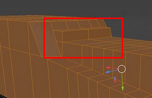
Right now you are way off with proportions and have too much geometry so it gets harder to move everything. It’s easier to move 3 vertices into their positions than 20 vertices, so you should not have loops where they don’t contribute to the forms. Also you got some forms completely wrong like the top part near the front window:
I would get rid of these edge loops:
The ones on the straight part just don’t do anything, and the ones where the bending starts would be OK, but it’s just such a hassle to move them and adjust them so I would want less and I can probably get away with less.
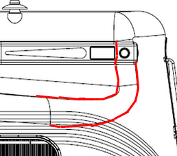
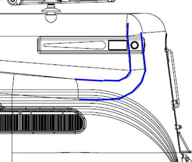
The proportions here are wrong if you have a look at where the bending starts(blue) after the straight line(red). This means that you have wrong depth of the sticking out part:
The depth is not changing until the bending starts at the very end only.
I am not really sure how to communicate this. I realize that the skill of seeing the proportions in forms doesn’t just appear out of nowhere instantly. I always notice and compare the sizes of forms and shapes when modelling, maybe that can be helpful. Try to compare the features like straight lines and curves in size to what you see in the references amongst themselves and also compare them to what you have.
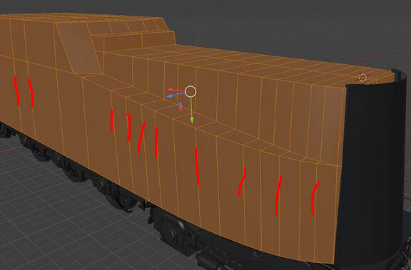
Like for example the bevels:
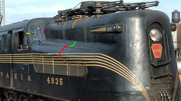
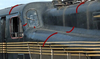
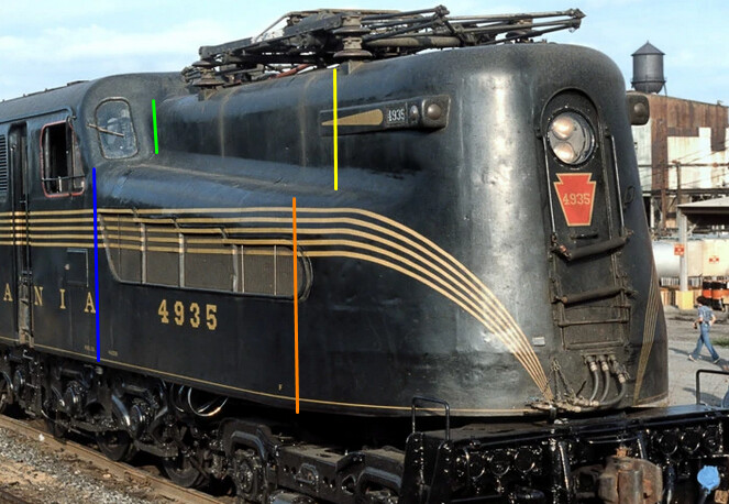
You don’t need to measure them(which if you could you most definitely should by the way) to see that the red one is probably the biggest one, the green one could be more than 2 times smaller and the orange one is very similar to the red one, the yellow one is similar to the purple one, maybe very slightly smaller, and they both maybe around 2 times smaller than the green one. The blue one seems not to be uniform and seems to get wider as it goes down as well. This is useful information. Same way with distances:
I would constantly compare the distances and features of forms in the reference. The drawing is useful, but since you have photographs of the real thing, that’s even more useful. You can actually measure the bevels and distance in the drawing or have it as reference in 3d, but it’s also quickly clear that the drawing is not accurate, or should I say the actual manufactured forms are not accurate to the drawing:
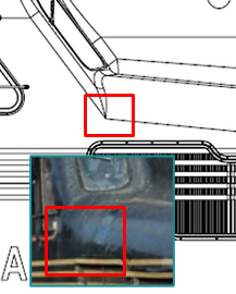
That’s clearly very different as there is no sharp corner on the actual train for example. Then you compare your results to the drawings and the photos this way. At least I would do that really a lot. Like hundreds of times with everything I can think of or see. And it gets more accurate as you go. The importance of getting the big basic forms is very strong as those forms will determine if the detail is possible to model realistically, so it’s worth to put more effort when looking at the biggest most basic forms.
This is actually really helpful suggestion I did not see at first. Making topologyfollow that would be a very good idea.
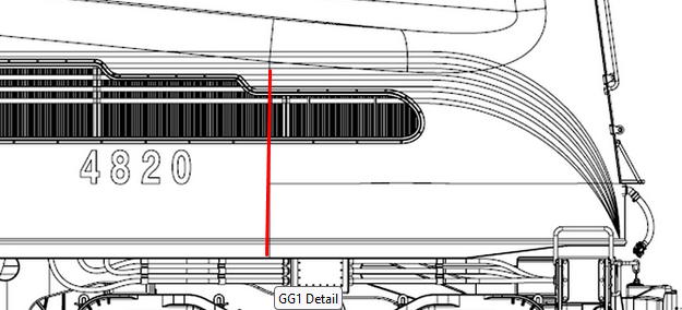
And I think this shows where the bending starts precisely. So it’s like constant comparing and then little bits of information help you define forms all around better and better.
What if I wrap a mesh about the contours of the train, add a subdivision modifier to it, and then use a voxel remesh to fix the topology, and dissolve the edges?
You are missing the forms. It’s best to always have the reference on screen and even in your 3d scene so you can clearly see. PureREF is your friend.
I’ll try to do a tiny bit, and walk through the process.
First of all let’s start with the most basic big forms. The front is angled and it has some subtle detail that is probably OK to have from the start:
I also added a loop so I know where the big rounding form at the front starts. You can barely see that the front windows are angled in the photographs and it is clearly visible in the drawing as well, so let’s add that as well:
The front has sort of an elliptical, maybe slightly irregular shape roundness with the front flattening a bit maybe, so I try to make sense of it as a whole and it would be hard to do on the model, so I make myself some temporary geometry for it. I make it out of a plane by beveling vertices and scaling them:
OK, so now I can attempt to arrange my geometry into that shape, maybe add a few extra loops to hold the forms(not sure if this is going to work yet, we’ll see):
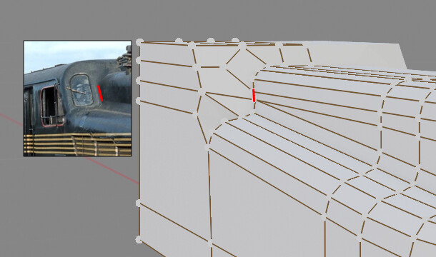
So it’s easy to do since I only have a few edge loops and I can move them manually quite easily, but I already see a problem with the form not matching in photos and the drawing(blue arrow), so I’ll just keep that in mind maybe smooth that out a bit later and there is a problematic place where all the bevels merge to smooth form and I know I’ll want the bevel to transition there like in the drawing so that’s going to be some manual vertex moving I am not sure about yet:
I work up some courage and add the first bevel keeping it about one third of the depth of “the sticking out side”, because I guess that may be about right…
So far so good, let’s add another bevel:
<sarcasm>Wonderful! Just how I like them! </sarcasm> But I have the long part with a nice regular form, so that’s what I wanted. Let’s merge some verts and make some topology that will hopefully make some sense. … I hope…
I merged some random vertices, added a loop cut to the front, made a mess in the blue rectangle and there is not enough geometry in the red one, so I’ll have to add another loop. The amount of vertices to move around grows rapidly, but I’ll try to be OK with it for now.
I tried adding another loop, realized, I don’t need it and just moved some loops around to make the geometry distributed a bit more evenly. Loop tools add-on has relax feature that smooths edge loops taking curvature into account, so I used that a couple of times on a couple of loops. Seems OK to me. Except of course for the fact that I would redo it because I failed with the size of the bevels as it’s visible from this distance:
So I would redo the last few steps or if I was smarter I could use some add-on to readjust the bevel, but I am not and I don’t model forms like this often enough to have those add-ons, so it would be just re-doing for me with this one. A bit less efficient in terms of time, but still works for me.
I think you should attempt to look at the reference more closely and direct your attention to smaller detail and try to concentrate on proportions more.


