How to import Nurbs surfaces into OBJ while preserving topology.
introduction
This is a short guide that allows you to import simple Nurbs models in IGES format into Blender, preserving the original topology of the surfaces with the original control cage, without having triangulated surfaces or NGons.
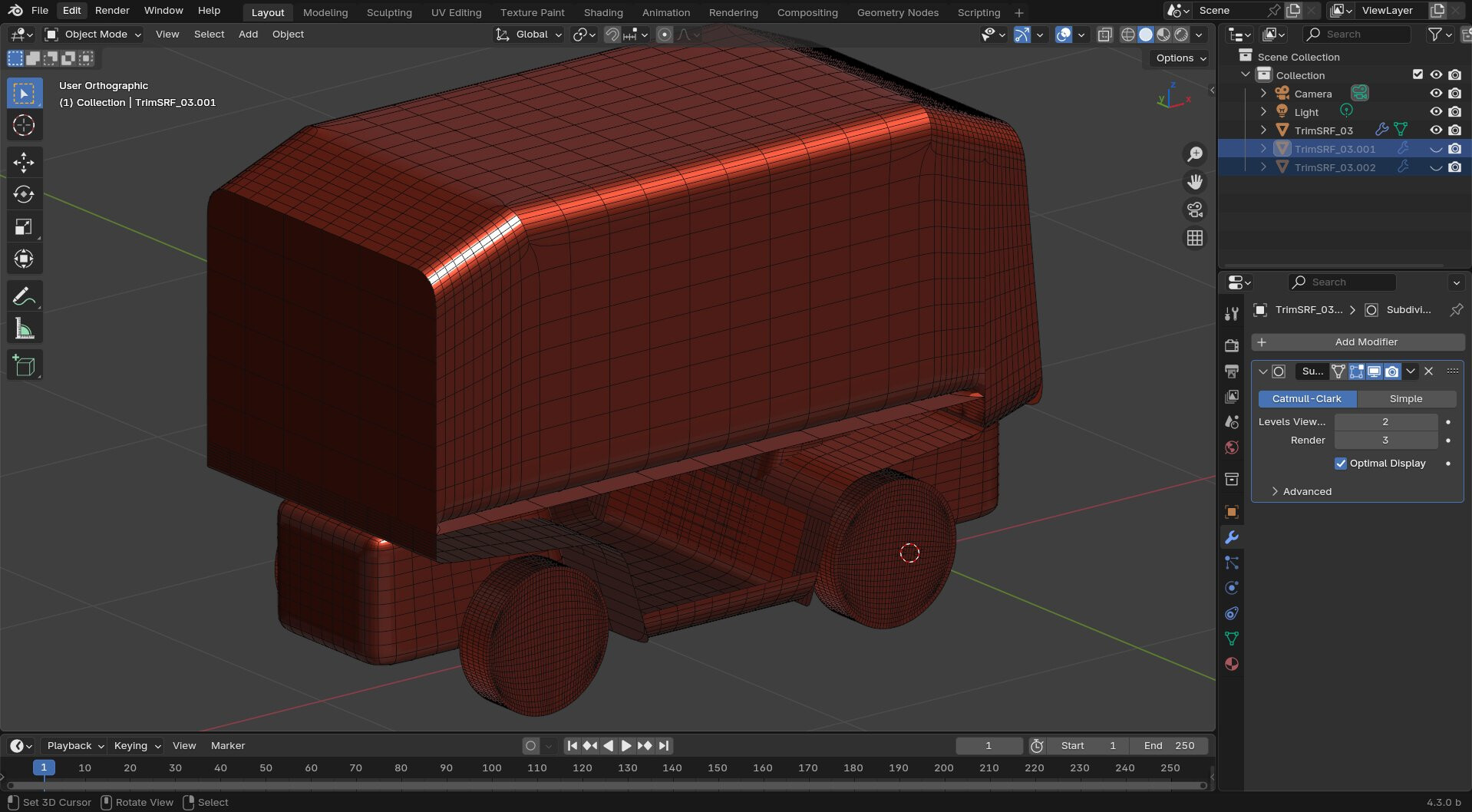
Importing Nurbs surfaces with the same original topology allows you to use the subdivision surface modifier in Blender.
This method can help in some cases but for complex objects it is advisable to use other methods such as some add-ons that allow the conversion of CAD files that generate the Quad topology.
Limitations
- This method does not support trimmed surfaces
- it is difficult to manage overly complex and large models
- surfaces with too high CVs density.
- Sometimes it is not possible to import IGES models correctly.
Required software
PolyCAD is a specific application for the design of nautical hulls, with several specific functions for calculations and CAD drawing, it is an application that can import IGES surfaces and also allows you to create them, it has basic commands, but essentially you can create many elements and perform various operations, as well as using it as a modeler of IGES files, in fact you can create patches with lofts, blends and ruled, as well as making conversions in various ways, although it may seem limited, it has everything to make CAD models, but it is specifically designed for sailing.
PolyCAD is free but you will have to register to use it, and unfortunately the activation lasts about 30 days and once the deadline has expired you are forced to activate again, this is something new that has been introduced a few months ago and it is boring but that’s how it is, let’s hope that the author increases the too short period, and brings it to at least one year.
FreeShip, as you can imagine from the name, is another application for nautical design, and uses subdivision surfaces as geometry, and also exports to IGES as explained in this old post, but in this case it will be used to import the .geo files of PolyCAD.
I’ve done some tests and with Plasticity there are always problems with IGES files, but with Moi3D and FreeCAD or gCAD3D things are better, furthermore Plasticity has its own philosophy with planar surfaces and always exports them as square patches with cut edges,
it doesn’t matter what the topology of the surfaces is, even if the surfaces are created with alternative solutions or with the square command but have all the control vertices aligned on an axis, these will be automatically converted into trimmed square patches, while with Moi3D and FreeCAD or other Nurbs modelers this does not happen and the original topology is maintained, and you can import these files without problems into PolyCAD.
The ability to use an original topology allows us to create complex objects without using trimmed surfaces because PolyCAD currently only imports IGES v5 and does not support trimmed surfaces.
However, you can also edit and reconstruct these surfaces in PolyCAD with internal commands and have surfaces suitable for the subdivision surface modifier in Blender or other software.
Steps to import OBJ into Blender.

This is the model that I’ve edited a lot and rebuilt surfaces for a quad topoloy
Import IGES files into PolyCAD, and if you are familiar with the program you can create or modify models with internal commands, save the file in the native PolyCAD format .geo
PolyCAD with model edited in Moi3D
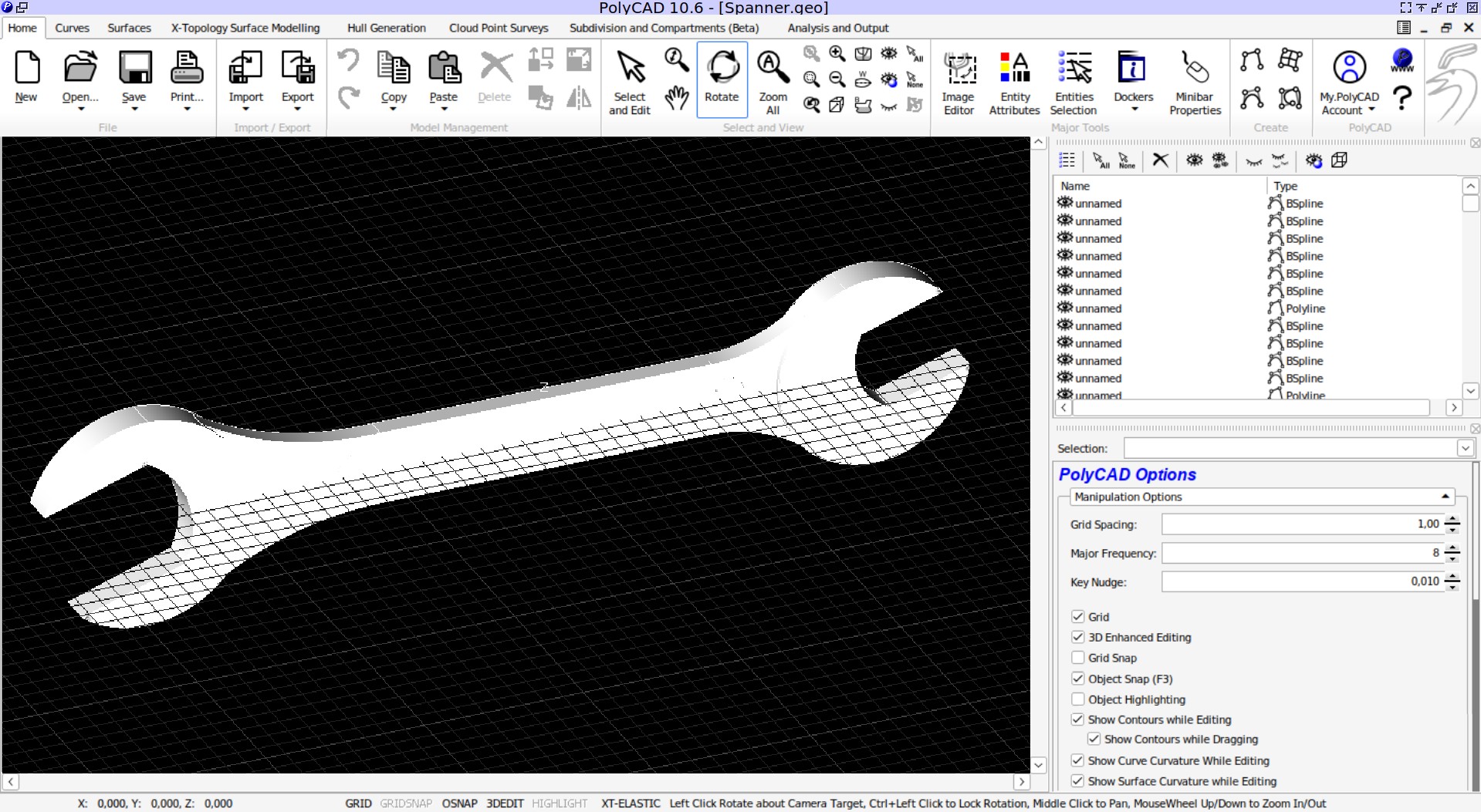
PolyCAD file source
Spanner.geo (127.5 KB)
Open FreeShip and import the PolyCAD file and in the project settings select the Precision on low, this avoids increasing the density of the surfaces too much making the model light, you can also convert or save the model directly from PolyCAD in VRLM 2, but they will still be triangulated although you can then change the topology to Quad with Blender using the Alt J command, but you will not always be able to obtain good results, so it is preferable to do it with FreeShip, which with the OBJ format always generates a Quad topology.
PolyCAD model imported in FreeShip without edge creases
In FreeShip you can also force creases edges with the command found in the application’s drop-down menu Edge → Crease.
FreeShip with Nurbs surfaces that have the same number of control vertices in one direction will be merged and you will either have to separate them or simply set the edge as Edge Crease.
FreeShip with Nubrs surfaces that have the same number of control vertices in one direction will be merged and you will either have to separate them or simply set the edge as Edge Crease.
To select an edges loop, hold down the SHIFT + CTRL keys and press the left mouse button over a segment.
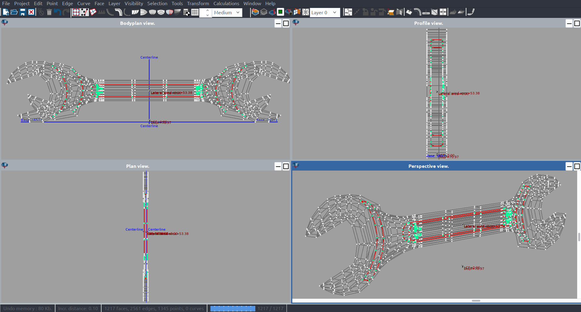
Model with edge Crease in FreeShip

FreeShip model
Spanner.fbm (77.0 KB)
Of course this is a solution that has many drawbacks but sometimes it could solve some problems and it is one more alternative that you can use in your modeling process, especially when a Quad topology is required otherwise if it is just a matter of Rendering all this it is not needed.
Below are my tests.
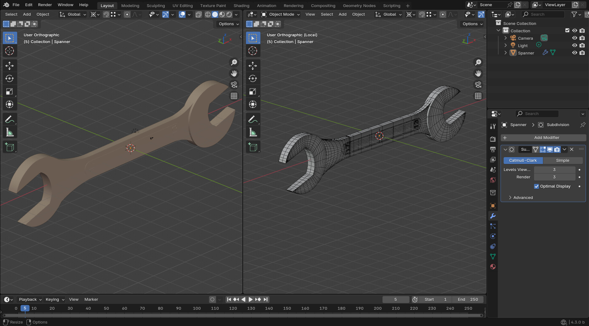
Blender file
Spanner.blend (836.0 KB)
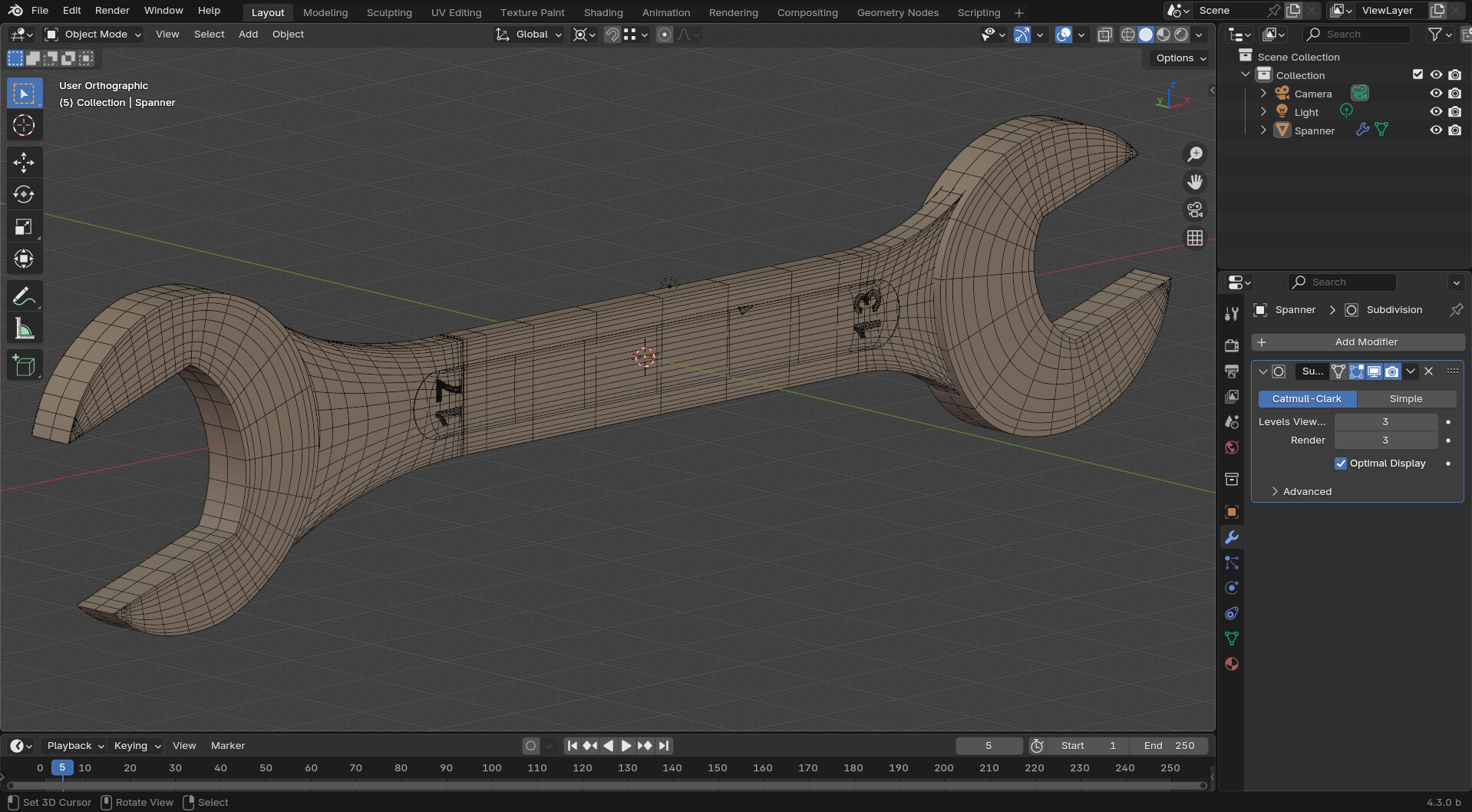
simple model with quad
hull model without edges loops but works

Additional tools with Moi3D
Rebuild Surface Script
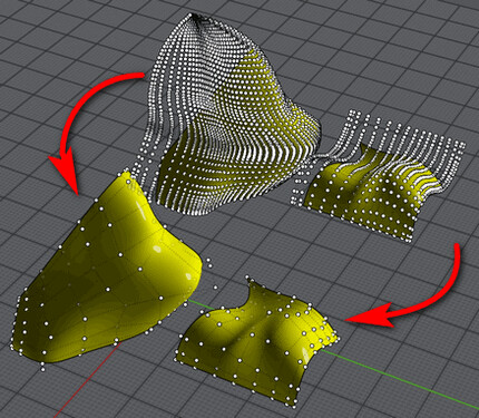
For those who have Moi3D this script allows you to reconstruct the surfaces in order to simplify them and allow a decent conversion, and will allow you to obtain excellent results, because you will be able to control various parameters and reconstruct the trimmed surfaces in such a way as to have a quad topology, in a surface , excellent for subdivision surfaces.
Although Plasticity has the ability to create excellent CAD surfaces, it is not like Moi3D which allows you to create surfaces with a particular topology, in fact with Moi3D you can always control the topology of your surfaces whether those are planar or more complex, Moi3D generates the patches Nurbs respecting the source curves, which is not possible in Plasticity, and this makes it less suitable, but it also has several problems with IGES files often not being exported correctly and other applications do not import Plasticity IGES files correctly, but with Moi3D this doesn’t happen.
So modeling the CAD files to then be converted into models and then applying the SubD modifier on top, makes Moi3D more suitable for this specific purpose.
Naturally this is a small expedient that is not easy to apply to overly complex models, because the work to be done could be too much, but on some it can be an alternative.